 English
 Arabic
 Chinese (Simplified)
 Dutch
 French
 German
 Italian
 Portuguese
 Russian
 Spanish

Understanding Impedance in AC Circuits: Capacitors and Inductors
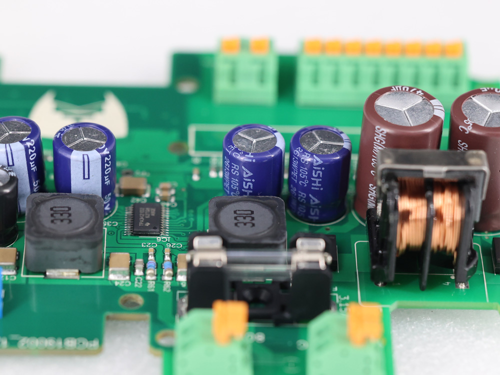
Introduction to Capacitor Impedance
Capacitors are essential components in AC circuit analysis, powering a multitude of everyday and industrial applications—ranging from filtering and coupling in audio circuits to energy storage in power supplies. While resistance is a familiar concept for DC circuits, in AC circuits, we encounter not just resistance but impedance, a complex quantity that embodies both resistance and reactance (opposition to changes in current flow).
Among all the types of impedance, capacitor impedance (also called capacitive impedance) stands out due to its unique, frequency-dependent behavior: unlike resistors, capacitors don’t dissipate electrical energy but instead store and release it, leading to interesting phase relationships and current-voltage dynamics.
Whether you’re analyzing an RC low-pass filter, troubleshooting a parallel RC circuit, or simulating an amplifier’s coupling capacitor, understanding capacitive reactance and complex impedance is crucial. This article will guide you through foundational theory, practical formulas, behavior at varied frequencies, calculation methods, and real-world implications for AC circuit design.
Defining Capacitor Impedance: Core Formula and Physical Meaning
Capacitor impedance, or capacitive impedance, measures how much a capacitor resists the flow of alternating current (AC)—but unlike a resistor, this resistance is frequency-dependent and includes a phase shift. In circuit analysis, impedance is represented as a complex number, capturing both the magnitude and the phase difference between voltage and current.
Core Formula
The impedance of a capacitor in AC circuits is given by:
[ Z_C = \frac{1}{j\omega C} ]
Where:
- (Z_C) = Capacitor impedance (ohms, Ω)
- (j) = Imaginary unit ((j^2 = -1)); in electrical engineering, (j) is used instead of (i) to avoid confusion with current.
- (\omega) = Angular frequency ((2\pi f)), measured in radians per second
- (C) = Capacitance in farads (F)
Physical Meaning and Magnitude
The absolute value (magnitude) of capacitive impedance is:
[ |Z_C| = \frac{1}{2\pi f C} ]
- At low frequencies (including DC, where (f = 0)), (Z_C) approaches infinity: a capacitor acts like an open circuit.
- At high frequencies, (Z_C) approaches zero: a capacitor acts nearly as a short circuit.
Phase Angle: The current through a capacitor leads the voltage by 90° (or π/2 radians), giving the impedance a phase angle of −90°. In polar form, this is denoted as:
[ Z_C = |Z_C| \angle -90^\circ ]
Table: Capacitor Impedance vs Frequency
| Frequency | Magnitude of (Z_C) | Typical Behavior |
|---|---|---|
| DC (0 Hz) | (\infty) | Open circuit |
| Low AC | High | Blocks low freq |
| High AC | Low | Passes high freq |
Capacitor Behavior at Different Frequencies
Capacitor impedance’s defining feature is its inverse relationship with frequency. Let’s examine what happens across the spectrum:
Low-Frequency (including DC)
- ( f \to 0 \implies |Z_C| \to \infty )
- The capacitor blocks current flow: it has charged up and resists any further DC current.
High-Frequency
- ( f \to \infty \implies |Z_C| \to 0 )
- The capacitive reactance becomes very small; the capacitor offers little “resistance” and lets AC signals through easily.
Why Does a Capacitor Block DC but Allow AC?
A DC voltage across a capacitor will charge it until the voltage across the capacitor matches the source, after which current ceases—hence, the open circuit at DC. With AC, the voltage is always changing; thus, the capacitor is alternately charging and discharging, allowing alternating current to flow.
Frequency Response and Resonance
In combination with inductors, capacitors create resonant circuits—filtering, passing, or blocking signals at specific frequencies. The frequency-dependent impedance is key to their use in filters, oscillators, and signal processors.
Capacitive Reactance and Impedance Calculations
Capacitive reactance (symbol: (X_C)) is the portion of a capacitor’s impedance that opposes AC current. Its formula is closely related to the impedance’s magnitude:
[ X_C = |Z_C| = \frac{1}{2\pi f C} ]
- Measured in ohms (Ω), just like resistance.
- Lower at higher frequencies, higher at lower frequencies.
Worked Example
What is the impedance of a 100 μF capacitor at 50 Hz?
[ C = 100,\mu{\rm F} = 100 \times 10^{-6},{\rm F} ] [ f = 50,{\rm Hz} ] [ X_C = \frac{1}{2\pi \cdot 50 \cdot 100 \times 10^{-6}} = \frac{1}{2\pi \cdot 0.005} = \frac{1}{0.0314} \approx 31.8,\Omega ]
Complex Form: [ Z_C = 0 – j 31.8~\Omega ] Polar Form: [ |Z_C| = 31.8~\Omega, \angle -90^\circ ]
This calculation confirms that a large capacitor at low frequency provides significant impedance, affecting how much AC can pass.
Capacitor Current–Voltage Relationship in AC
The fundamental behavior of a capacitor is captured by the current–voltage relationship:
[ i(t) = C \frac{dv(t)}{dt} ]
For a sinusoidal voltage (v(t) = V_m \sin(\omega t)):
[ i(t) = C \frac{d}{dt} [V_m \sin(\omega t)] = \omega C V_m \cos(\omega t) ]
- The current waveform is phase-shifted by 90°, leading the voltage.
Key Points:
- Current leads voltage: When voltage is rising, capacitor current is at a maximum.
- Voltage lags: The capacitor needs time to “catch up” to the rise in current.
Phasor Representation:
- Voltage and current are represented as rotating vectors (phasors).
- The current’s phasor is ahead of the voltage phasor by 90° in the complex plane.
Energy Storage:
- Capacitors alternately store and release energy as an electric field.
- In pure capacitors, no net energy is dissipated, only exchanged with the AC source.
Impedance in Series and Parallel RC Circuits
Real-world AC circuits rarely have just a capacitor—they often feature a series or parallel mix with resistors (RC circuits).
Series RC Circuits
Total Impedance: [ Z_{RC(series)} = R + \frac{1}{j\omega C} ]
- In rectangular form: ( Z = R – jX_C )
- In polar form: ( |Z| = \sqrt{R^2 + X_C^2} ), phase angle ( \theta = \arctan\left(-\frac{X_C}{R}\right) )
AC Ohm’s Law: [ I = \frac{V}{|Z|} ]
- Same current through both components; voltages add as vectors (phasors).
Parallel RC Circuits
Branch Currents:
- Resistor and capacitor each see the same voltage.
- Total current is sum of resistor and capacitor currents (vector sum).
Total Impedance: [ \frac{1}{Z_{RC(parallel)}} = \frac{1}{R} + \frac{1}{Z_C} ] Or, [ Y = G + jB ] Where (Y) is admittance, (G = 1/R) is conductance, (B = \omega C) is susceptance.
Example Table: Series vs. Parallel RC Impedance
| Circuit Type | Formula for (Z_{total}) | Phase Angle | Key Behavior |
|---|---|---|---|
| Series RC | (R – jX_C) | (\arctan{-X_C/R}) | Both elements share the current |
| Parallel RC | ((1/R + j\omega C)^{-1}) | Depends on ratio | Both elements share the voltage |
Real vs. Ideal Capacitors in AC Circuits
Ideal Capacitor
- Only stores and releases energy.
- No losses, infinite DC resistance, zero series resistance.
Real Capacitor
Every real capacitor has limitations:
- Equivalent Series Resistance (ESR): Tiny but nonzero resistance in series with the ideal capacitor, causes power dissipation and heating under AC load.
- Parallel Leakage Resistance: DC path due to imperfect dielectric or moisture ingress.
- Dielectric Loss: Some AC energy turns into heat, especially at high frequencies (quantified as dissipation factor or tan δ).
- Self-Resonant Frequency: Combined effects of ESR and equivalent series inductance (ESL) mean that above some frequency, the capacitor no longer behaves as expected.
Practical Effects
- Electrolytic capacitors may have large ESR; unsuitable for high-frequency or rapid-transient AC signals.
- Ceramic capacitors offer low ESR, good for decoupling and filtering in high-frequency circuits.
Table: Real Capacitor Considerations
| Parameter | Effect in AC Circuits |
|---|---|
| ESR | Energy dissipation, heat, noise |
| Dielectric loss | Decreased performance at high frequency |
| Leakage resistance | Signal loss, instability |
| ESL | Reduced |
Applications of Capacitor Impedance
Because capacitive impedance is frequency dependent, capacitors are invaluable in AC circuits for their ability to shape, filter, or tune signals:
- Filter Circuits: Low-pass, high-pass, and band-pass filters depend on frequency-variable impedance to pass or block specific frequencies.
- Power Factor Correction: Capacitors counteract inductive loads in AC power systems, improving efficiency and reducing losses.
- Coupling and Decoupling: In amplifiers and digital circuits, capacitors block DC bias while allowing AC signals (coupling), or smooth noise and ripple (decoupling).
- Tuned and Resonant Circuits: Used alongside inductors for precise frequency selection in radios (LC circuits).
- Energy Storage and Smoothing: In power supplies, large capacitors reduce voltage ripple and store charge for transient current spikes.
- Voltage Regulation and Spikes: Capacitors in voltage regulators absorb load changes and transient spikes.
- Motor Run Capacitors: Provide phase shift and efficient running for single-phase AC motors.
- RF Circuits: At RF, capacitors act as frequency-dependent elements for impedance matching, tuning, or bypassing.
Table: Common Applications for Capacitor Impedance
| Application | Capacitor Role | Why Impedance Matters |
|---|---|---|
| Low-pass filter | Bypass high frequencies | High freq: low (Z_C) |
| AC coupling | Block DC, pass AC | DC: high (Z_C); AC: low (Z_C) |
| Power factor correction | Lead current in AC load | Cancels inductive reactance |
| Decoupling | Filter noise/ripple | Bypass high-frequency noise |
| Tuning circuit | Selects specific frequency | Resonant at a set (f) |
Frequently Asked Questions
What is the capacitive reactance formula?
Capacitive reactance ((X_C)) is given by: [ X_C = \frac{1}{2\pi f C} ] It tells you how much a capacitor resists AC for a given frequency and capacitance.
How do I calculate capacitor impedance in AC circuits?
The full complex impedance is: [ Z_C = \frac{1}{j\omega C} ] where (\omega = 2\pi f), and in magnitude is equivalent to (X_C).
Why does current lead voltage in a capacitor?
In a capacitor, maximum current occurs as voltage begins rising or falling—current flows to create the changing voltage, hence the current leads by 90 degrees.
What happens at very low and very high frequencies?
At low (including DC): (Z_C) is very high; at high frequencies, (Z_C) drops and may approach zero (effectively a short).
How does real-world behavior (ESR, dielectric loss) affect circuit design?
High ESR or dielectric loss leads to less effective filtering, more heat, and potential performance issues—especially at high currents or frequencies.
How do capacitors work with inductors in AC?
Together they form resonant circuits, allowing frequency selection or rejection (e.g., radio tuning).
Conclusion
Capacitor impedance is foundational to AC circuit analysis—governing how capacitors function in filters, power supplies, audio, RF, and digital systems. Unlike resistors, a capacitor’s opposition to AC changes with both capacitance and frequency, causing unique phase shifts (current leads voltage) and enabling vital circuit behaviors like filtering and signal coupling.
Accurately calculating capacitive impedance, understanding the effects of ESR and dielectric loss, and selecting the right type of capacitor for the frequency range ensures robust, efficient circuit design. Whether you’re building a simple RC circuit or fine-tuning a radio receiver, knowledge of capacitive reactance, impedance, and frequency response will lead to better performance and reliability in every application.