 English
 Arabic
 Chinese (Simplified)
 Dutch
Dutch French
 German
 Italian
 Portuguese
 Russian
 Spanish
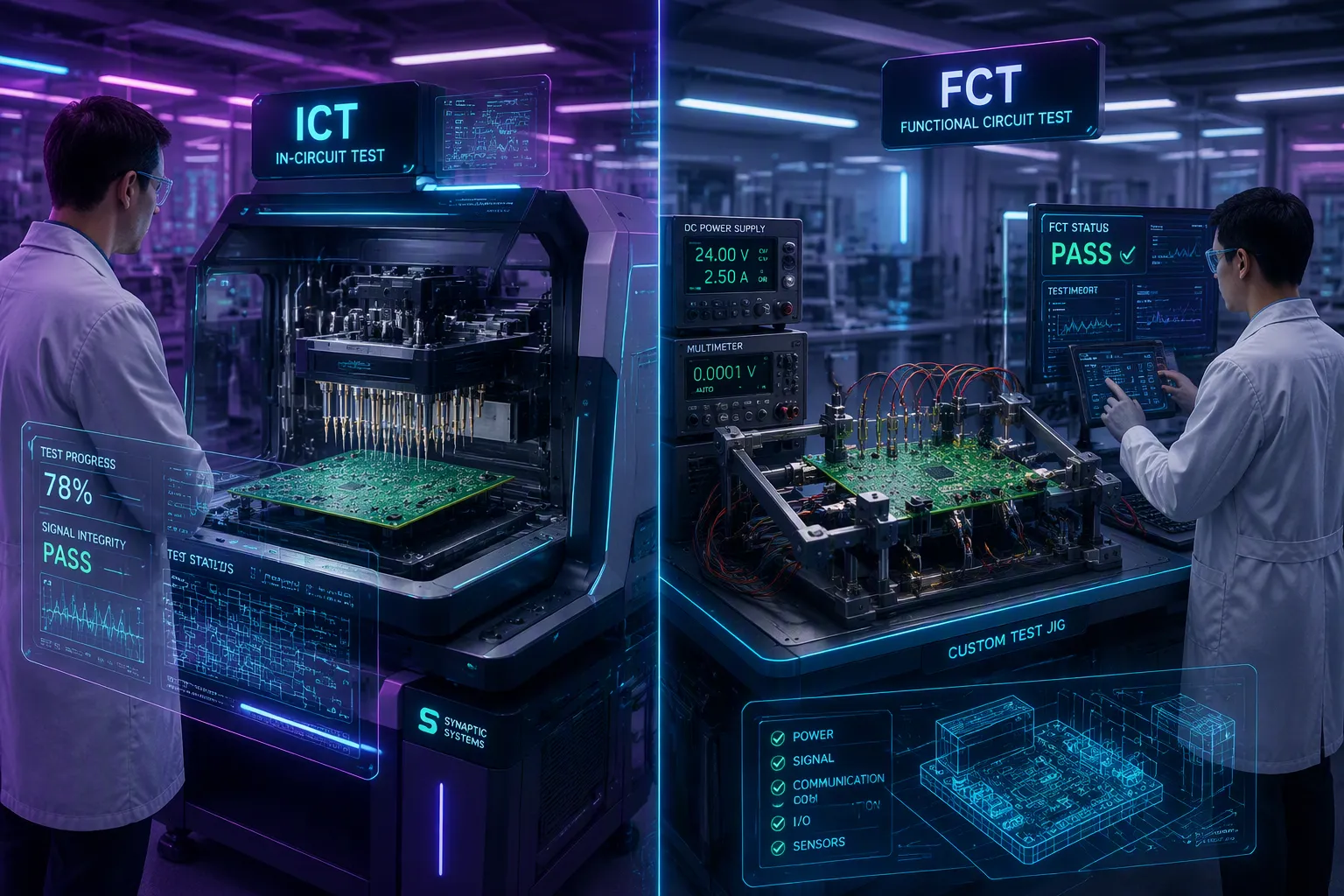
Testing plays a key role in pcba manufacturing—it keeps products reliable and customers happy. For ict fct full functional test pcba, the two methods differ in three main ways: purpose, test coverage, and cost/speed. This guide helps you choose based on your production stage, volume, and quality goals.
Do you need to find a broken wire or prove the whole device works? ICT checks component placement and circuit connections early in manufacturing. FCT checks how the product performs as a whole.
Overall product functionality is the key on FCT, I agree that all others can be performed at ICT but ICT sometimes can’t perform a real functional test specially load test or even can’t perform safety or regulatory test.
Together, these pcba testing methods boost first-pass yield and cut down on rework.
Key Takeaways
- ICT finds build mistakes early. FCT checks if the whole product works.
- ICT tests each part closely. FCT tests the whole system in real conditions.
- ICT costs more to set up but tests fast. FCT costs less but tests slow.
- Use ICT for high volume. Use FCT for low volume or complex boards.
- Combine ICT and FCT for best quality. This reduces recalls and improves reliability.
Core Purpose: Component vs. System Verification
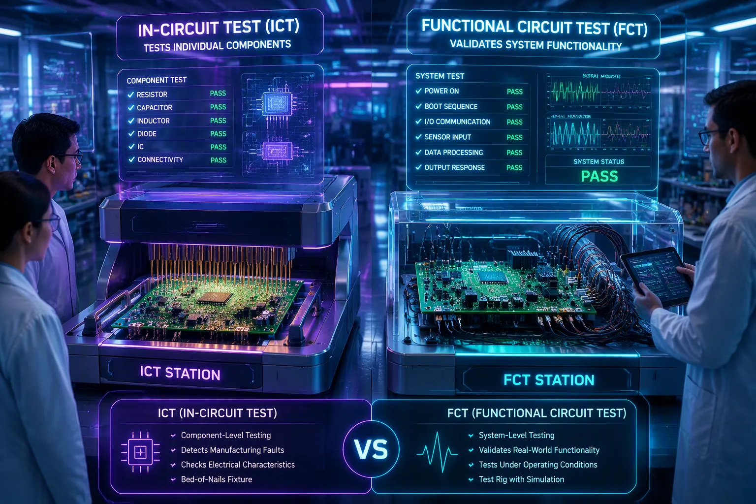
The first big difference between ICT and FCT is what each test checks. Think of in-circuit test like a microscope and functional circuit test like a flight simulator. One looks at tiny details up close. The other puts the whole machine through real actions. Knowing this helps you pick the right test for your line.
ICT: Catching Manufacturing Defects
ICT happens early in manufacturing. It finds structural problems before they move on. A “bed of nails” fixture presses spring-loaded pins onto test points. These pins measure electrical values at each part.
This method finds physical assembly errors very well. Here are the main defects ICT catches:
- Open circuits — broken traces or bad solder joints that stop the current
- Short circuits — unwanted connections, like solder bridges, that cause too much current
- Poor solder joints — weak connections or cold joints that make high resistance
- Missing parts — components that were never placed on the board
- Wrong polarity — reversed capacitors, diodes, or other parts that need correct orientation
ICT also checks part values. A resistor with wrong rating, a capacitor with wrong capacitance — these stand out during probing. For high-volume runs, ICT gives great coverage. Typical systems catch about 80% of structural faults and 90% of electrical faults.
ICT fixture testing checks key circuits like power, ground, and high-frequency signals. By testing both endpoints, ICT stops short-circuit defects from reaching later stages or customers.
The main point: ICT answers “Is the board built right?” It does not tell you if the board works in the real world.
FCT: Validating End-User Functionality
FCT comes later. You power up the board and mimic real conditions. The goal shifts from checking parts to checking system behavior. You want to know: “Does this pcba do what the customer expects?”
FCT checks several important areas:
- Power supply checks — voltage regulation, current draw, and proper power-on/power-off sequences
- Input simulation — signals from sensors, buttons, or communication ports
- Output validation — digital states, analog signal quality, and data transfer speeds
- Overall functionality — a pass/fail decision that the board works as designed
FCT also tests software and peripheral interactions. Firmware flashing and checking happen here. Sensor calibration, ADC tuning, and power regulator setup happen during this stage. You physically test buttons, LEDs, and displays. Communication ports — USB, Ethernet, CAN — get tested with real traffic.
The simulation depth depends on the industry. Here are some examples:
| Real-World Condition | FCT Simulation Method | Industry Example |
|---|---|---|
| Extreme temperature (-40°C to 125°C) and vibration | Environmental chambers built into FCT setups | Automotive PCBA testing |
| Electromagnetic interference (EMI) | EMI shields in FCT fixtures | Medical device PCBA testing |
| High voltage (up to 1200V) and high current (up to 40A) | Variable power supplies | Renewable energy PCBA testing |
| Voltage changes and power cuts | Variable power supplies that mimic electrical stress | Consumer IoT devices |
| Tight space inside the product case | Modular fixtures that copy the small enclosure | High-volume PCBA assembly lines |
Special devices need custom tests. Bluetooth modules need RF checks and pairing tests. Battery management systems need charge/discharge cycles. Industrial I/O boards need relay control and isolation tests. FCT adapts to each product.
The core difference: ICT checks component functionality alone. FCT checks overall functionality in the whole system. One checks the parts; the other checks the whole. Both are important in pcba testing, but they answer very different questions about your product.
Test Coverage: From PCBA Components to System Behavior
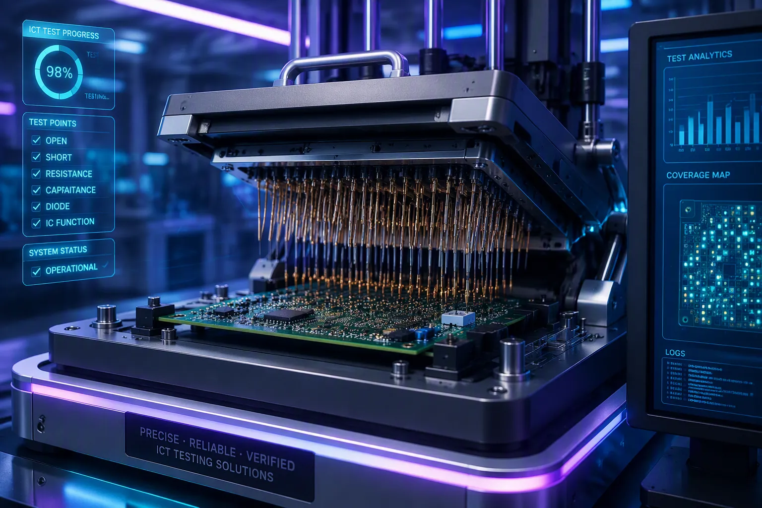
The second big difference between these two tests is how much of the board each one checks. Think of test coverage as a range. On one end, you have very fine detail. On the other end, you have the whole system working. Knowing where each test fits on that range helps you build a smarter testing plan.
ICT’s Pin-Level Precision
In-circuit test gives you very accurate results at the single-part level. The bed-of-nails tool uses spring-loaded pins that press against test points all over the board. Each pin touches one node, so the system can measure voltage, current, and resistance at that exact spot. This parallel checking happens across hundreds or thousands of points in just a few seconds.
The fixture design matters a lot for boards with many parts. You have several ways to press the board down:
- Clamshell actuation uses a hinged lid, but the angled closing makes the pins slide, which lowers accuracy
- Vertical actuation moves straight down for the last 10mm, so pins do not slide, giving better accuracy for tiny test points
- Vacuum actuation pulls the board down onto bottom-side probes, useful when you need both sides tested
- Pneumatic actuation uses air cylinders for steady force, making automation and repeatable contact possible
Probe pitch sizes range from 100-mil standard down to 15-mil ultra-fine for the hardest jobs. You should not have more than 12 test pads per square inch to keep the board flat. Gold-plated beryllium copper pins usually last 100,000 to 500,000 cycles.
This accuracy leads directly to finding faults. ICT catches 90% to 98% of manufacturing defects. That means you find problems early, before they travel through your whole production line. Industry expert Kishore Mupparaju says catching defects early cuts waste, lowers rework, and improves first pass yield.
FCT’s Full-System Simulation
Functional circuit test uses a very different method. Instead of testing single pins, you power up the whole board and watch how it behaves. You copy real-world conditions and check that the whole system works as designed.
FCT finds complex functional problems that ICT cannot catch. Software compatibility, firmware interactions, communication protocols, and peripheral responses all fall under FCT’s area. You test USB ports with real traffic, check CAN bus communication, and confirm that sensors respond correctly to input.
The fault coverage comparison tells an important story:
| Test Type | Fault Coverage for Manufacturing Defects |
|---|---|
| ICT | 90% to 98% |
| FCT | Lower than ICT |
But FCT catches a different type of problem. It checks that the whole system works under simulated operating conditions. Temperature testing checks performance in high or low heat. Reliability testing simulates long-term use through thermal cycling, vibration, and shock.
Industry experts agree you need both. Yueming Chen says that for high-reliability products, ICT plus FCT is not an extra option—it is a required quality standard. FCT alone misses hidden soldering flaws that cause failures later in the field. ICT alone cannot simulate real operating scenarios or software functions. Together, they give reliable, high-quality electronic products by catching defects early and checking final performance.
Cost and Speed: Trade-Offs in ICT vs FCT for Full Functional Test PCBA
The third big difference between these test methods is about money and time. Your budget and how many boards you make will decide which one to use. Knowing the costs helps you avoid wasting money on the wrong test plan for your ict fct full functional test pcba line.
ICT: High Setup Cost, Fast Cycle Time
ICT needs a large upfront payment. The bed-of-nails fixture must be custom-made for each board design. Writing the test program adds more cost. Industry data shows PCB in-circuit testing setup starts at $10,000 and can go over $50,000, with an average cost near $20,000. This amount covers fixture building and programming.
| Cost Component | ICT | FCT |
|---|---|---|
| Fixture development | $10,000 – $20,000 | $5,000 – $15,000 (basic bench) |
| Programming / custom gear | $1,000 – $3,000 | $2,000 – $10,000 |
| Total setup cost | $11,000 – $23,000+ | $7,000 – $25,000 |
But the cost per board is different. ICT tests a board in just seconds. The fast speed means you can push thousands of units through each day. For high-volume production, the big initial cost spreads across many units, making each test very cheap. This makes ICT a good deal for large batches where finding defects early saves money on rework and scrap.
FCT: Lower Setup Cost, Slower Throughput
FCT needs a simpler fixture design. You do not need hundreds of spring-loaded pins touching every node. A basic bench setup costs less to build. The lower one-time engineering costs make FCT attractive for smaller runs.
But FCT takes much longer per unit. Industry sources say FCT usually takes five to ten times longer than ICT for the same product. Each board needs power-up, signal simulation, and behavior checks. This slower speed raises the cost per unit. For low production volumes, using FCT alone may work fine, since spending on dedicated ICT fixtures may not be worth it.
ICT costs a lot upfront because of special equipment and skills. FCT saves money because it tests the whole assembly, so you do not need expensive system-level testing.
Many manufacturers use both tests together. They run ICT first to catch structural defects quickly, then use FCT to check system function. This combined method gives the best coverage while balancing cost and speed. One ICT machine can feed several FCT fixtures at the same time, increasing test speed and reducing delays. For high-reliability fields like medical or automotive, this dual approach ensures both structural integrity and functional correctness in your pcba manufacturing process.
ICT gives you fast, precise screening for manufacturing defects. FCT delivers slower but comprehensive validation of system functionality. Choose ICT for high-volume production where early defect detection saves money. Choose FCT for low-volume, complex assemblies where verifying end-user experience matters most.
For regulated industries like automotive and medical, combine both methods. Run ICT first to catch assembly errors, then FCT to validate system performance. This sequential approach directly reduces recalls and improves reliability.
Your strategic choice between ICT and FCT impacts product quality, time-to-market, and production efficiency. Match your testing plan to your volume and quality goals for the best ict fct full functional test pcba outcome.
FAQ
Can you replace ICT with FCT entirely?
No. You cannot swap ICT for FCT completely. FCT checks system behavior but does not find build mistakes. ICT catches those early. Use both in your ict fct full functional test pcba process.
How do you choose between ICT and FCT?
Think about how many boards you make and your quality goals. Use ICT for high-volume lines where fast defect finding saves money. Use FCT for low-volume, complex boards. Many manufacturers combine both for best coverage.
What is the difference in test coverage?
With ICT, you test each part at the pin level, catching 90-98% of build mistakes. With FCT, you test the whole system in real-life conditions, finding functional problems. Both are important in pcba testing.
Which test is faster?
ICT is much faster. You can test a board in seconds. FCT takes five to ten times longer because it copies real-world use. ICT gives high throughput, while FCT does a thorough check.