 English
 Arabic
 Chinese (Simplified)
 Dutch
Dutch French
 German
 Italian
 Portuguese
 Russian
 Spanish

Solder beading defects at 0.4mm pitch ball grid array components cause electrical shorts, reliability failures, and yield loss. Preventing these defects requires a coordinated approach across pcb manufacturing, from pad design to stencil engineering and reflow profiling. This article provides parameter-specific guidance on PCB design rules, stencil thickness, and bga assembly process optimization. You will learn how to control solder volume, minimize outgassing, and reduce warpage for BGA joints to prevent defects. These steps improve production quality. Follow them to achieve a beading-free assembly.
Key Takeaways
- Use a 0.1mm stencil so the aperture area ratio stays above 0.66, which helps solder paste release reliably.
- Make NSMD pads with a solder mask dam width of 0.075 to 0.1mm to stop solder bridging.
- Control the reflow profile by soaking for 60–90 seconds and keeping the peak temperature under 260°C. This helps reduce warpage and outgassing.
- Choose Type IV solder paste and nano-coated stencils. This helps paste move better and stops clogging.
- Use X-ray inspection to check your assembly process. This helps find hidden flaws and supports perfect soldering.
Why Solder Beading Occurs on 0.4mm Pitch BGAs
The 0.4mm pitch leaves little room for mistakes in the BGA assembly process. The space between nearby BGA pads is very small. This tight gap leaves almost no space for extra paste. Even a small extra amount of paste can form a bead that harms the solder joint. Knowing the root causes helps you manage the assembly.
Excessive Solder Volume and Paste Release Defects
The main cause of beading is too much material placed on one pad. Your stencil design controls the solder paste volume. The stencil aperture area ratio must stay above 0.66 for good paste release. When the ratio drops below this number, paste release becomes uneven. Some openings put down too little solder paste, while others put down too much. The large deposits collapse during reflow and create beads. These beads often cause solder joint bridging between nearby pads.
Poor paste release from stencil openings creates another issue. Sticky residue blocks the openings over time. This blockage causes random changes in paste volume across the BGA. The change makes some pads get a large deposit. These large deposits push out from under the BGA package and form solder balls. The outcome is a failed connection.
Outgassing and Component Warpage During Reflow
Outgassing during reflow also adds to beading. Your solder paste flux has volatile compounds. The temperature goes up during the soldering process. These compounds then evaporate quickly. The fast outgassing can push small particles out of the paste deposit. These pushed-out particles land on the PCB surface and form solder balls. A close look at the reflow profile shows when outgassing happens.
Component warpage adds another risk. The ball grid array package and the PCB grow at different rates during assembly. This difference causes the BGA to warp. Peak reflow temperature makes the warpage lift the edges of the component. The lifted edges create a gap. This gap lets molten material escape. The escaped material then hardens as unwanted solder balls on the PCB. You need careful thermal checks to stop this problem.
PCB Manufacturing Design Rules for Pad and Mask

Your pad design choices in pcb manufacturing decide if solder beading shows up under a 0.4mm pitch bga. Non-solder mask defined (NSMD) pads leave the copper pad fully exposed. This helps solder wet better and lowers voiding. But at 0.4mm pitch, the mask opening uses up valuable space between nearby pads. This leaves a thin solder mask dam that can peel during reflow. When the dam fails, melted solder moves freely across the gap. This creates bridges or beads.
NSMD Pads and Solder Mask Expansion for Fine Pitch
You must control the solder mask dam width with care. Industry rules call for a dam width of 0.075–0.1 mm for fine-pitch parts. This physical barrier stops melted solder from crossing between nearby pads during reflow. A narrower dam cannot hold the solder back. This greatly raises the risk of bridging.
- Keep at least 225 μm between mask openings to stop solder bridging during reflow.
- NSMD pads allow looser mask-to-pad alignment, which makes assembly faster.
- Without tight control of mask opening spacing, solder beading becomes more likely.
The alignment accuracy of your solder mask matters just as much as the dam width. NSMD pads handle looser alignment tolerances. This helps your assembly process. Yet at 0.4mm pitch, misalignment moves the mask opening. It also shrinks the usable space between exposed copper areas. This misalignment can make the thin mask web lift during reflow. The exposed copper then becomes open to bridging. This directly leads to beading defects.
Pad Size Consistency and Surface Finish Selection
Steady pad sizes across the whole bga footprint ensure even solder paste placement. When pad sizes differ, some spots get too much paste while others get too little. The larger deposits collapse during reflow and form beads. You should set tight limits on pad diameter in your pcb fabrication drawings.
Your surface finish choice also changes beading behavior. Electroless nickel immersion gold (ENIG) gives a flat, wettable surface. This promotes even solder flow. Organic solderability preservative (OSP) offers a cheaper option with good coplanarity. Both finishes support steady wetting across all solder pads. Stay away from finishes with uneven surfaces. They create local differences in solder spread.
The link between pad design and stencil openings sets your final solder volume. You must check that your pad shape matches your stencil openings during the design review phase. This check in the manufacturing process finds mismatches before they turn into costly defects. A full design for manufacturing review stops beading at the source. This beats fixing problems later.
Stencil and Solder Paste Optimization for BGA
Your stencil design controls how much solder reaches each pad. For a 0.4mm pitch bga, set the stencil thickness to 0.1mm. This keeps the aperture area ratio above 0.66. The IPC-7525B standard requires this level for all fine-pitch SMT apertures. At 0.4mm pitch, the bga pads are only about 0.25mm wide. This small size makes the area ratio drop below 0.66 easily. A 0.125mm stencil with a 0.3mm aperture gives an area ratio under the limit. Reducing the stencil to 0.1mm brings the area ratio to 0.75. This value confirms good paste release for your bga stencil.
Keep the aperture at 1:1 with the pad or use a small 5-10% reduction. Do not shrink the aperture below 90% of the pad size. A smaller aperture starves the joint of paste. This raises the risk of misplaced paste and later solder balls. The area ratio also affects consistency. Even tiny tolerance errors of ±0.01mm can shift the area ratio enough to cause defects. Tighter aperture registration and a clean stencil underside stop paste from landing outside the pad. This lowers the chance of solder balls and solder bridges forming during assembly. The solder must spread evenly across the solder pads for a reliable connection.
Stencil Thickness and Aperture Area Ratio
The stencil thickness must balance paste volume with release reliability. With a 0.1mm stencil, you get enough paste for a strong solder joint. Excess solder causes beading defects. The aperture area ratio uses the aperture wall area and the opening area. For a circular aperture, divide the opening area by the wall area. A ratio above 0.66 ensures steady paste release from the stencil to the pcb pads. When the ratio falls below 0.66, paste sticks to the stencil walls. This creates uneven deposits. Some pads get too much solder. Others get too little. The large deposits collapse during reflow and form beads or bridges between nearby solder pads. A reliable solder joint needs careful control of the whole process.
Solder Paste Selection and Stencil Coatings
Pick a fine powder suitable for your bga assembly and fine-pitch assembly. The smaller particles pass through fine apertures more easily. This reduces clogging and boosts transfer efficiency. The choice of flux is vital for this process. The flux must activate fully during the soak zone without leaving extra residue. Extra residue attracts moisture and can cause outgassing during reflow. This outgassing pushes out small particles that form unwanted solder balls on the pcb surface.
Stencil coatings improve paste release and reduce aperture clogging. Two common treatments are electropolishing and nano-coating. The table below compares their effects.
| Metric | Electropolishing | Nano-Coating |
|---|---|---|
| Primary Mechanism | Electrochemical smoothing of aperture walls to remove burrs and slag | Adds a low-friction, hydrophobic fluorosilicone polymer layer |
| Effect on Paste Release | Reduces mechanical resistance for cleaner separation | Provides a non-stick surface for cleaner release and less residue |
| Cleaning Interval | Can improve release and reduce residue | Extends from 3-5 prints to 20-60 prints |
| Quantified Benefit | Smoother walls for fine-pitch apertures | Up to 30% improvement in transfer efficiency; surface roughness Ra of 0.08-0.15 µm |
| Relevance to 0.4mm Pitch BGAs | Addresses rough walls that can cause starved deposits or bridging at fine pitches | Specifically recommended for BGA/QFN assemblies to prevent clogging and smearing, improving first-pass yield |
Nano-coated stencils improve solder paste transfer efficiency by up to 30% compared to uncoated ones. This leads to more even deposits on pads smaller than 0.25mm. The better release directly lowers the chance of defects. For boards with fine-pitch parts below 0.4mm, nano-coating ensures accurate paste application without clogging or smearing. The longer cleaning interval also means less paste residue buildup. This reduces a factor that adds to beading defects. Using coated stencils in your assembly process improves first-pass yield for every board. The mix of fine powder, suitable flux, and coated stencils gives you steady control over the bga assembly process. The solder flows smoothly, creating a defect-free result on each joint.
Optimizing the BGA Assembly Process: Reflow and Placement
Your reflow profile decides if the bga assembly process works at 0.4mm pitch. The thermal curve directly affects component warpage, outgassing, and solder flow. You must control each zone of the profile with care to stop defects that hurt solder joint quality.
Reflow Profile Parameters for Warpage and Voiding Control
The preheat zone sets the foundation for a good bga assembly. You should keep the ramp rate at no more than 3–4°C per second. Faster heating causes thermal shock that makes warpage worse across the part. The temperature difference between the bga center and its edges creates mechanical stress. This stress bends the package and pushes molten solder out during the process.
The soak zone needs your closest focus. This phase activates the flux and drives out volatile compounds slowly. A controlled outgassing stops violent bursts that throw solder particles onto the pcb. These thrown particles become solder balls that bridge nearby joints. Your soak parameters should follow these guidelines:
- Soak time between 60–90 seconds lets flux fully activate without using it up too early.
- Soak temperature range of 150°C–200°C gives enough heat for chemical reactions.
- An extended soak at 90 seconds cuts void formation by 30–40% compared to shorter profiles.
- Uniform heating across the board lowers temperature differences that cause warpage.
The peak temperature zone also needs careful control. You should keep the peak below 260°C to stop too much intermetallic growth and uncontrolled solder flow. Time above liquidus should stay within 90–120 seconds. Longer time creates brittle intermetallic compounds that weaken each joint. Shorter time leaves too little time for proper wetting and joining.
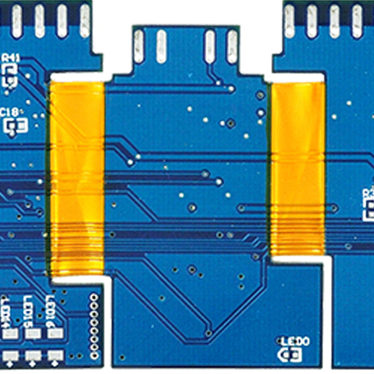
In a thick rigid-flex design, warpage caused head-in-pillow defects during first production. Engineers added a custom fixture for board support and lowered the peak temperature by 8°C while making the soak longer. This change fixed the warpage completely. The new profile became the standard for the whole product line. It shows how controlled peak temperature and soak changes can reduce warpage defects.
A nitrogen atmosphere during reflow cuts oxidation on both the solder paste and the bga pads. Cleaner surfaces help better wetting and lower the surface tension that pulls solder into beads. The controlled cooling rate also matters. Gradual cooling stops thermal shock that could crack newly formed solder joints.
Placement Accuracy and Post-Reflow Inspection
Your placement equipment must achieve tight bga placement accuracy before reflow starts. Misalignment can cause solder to squeeze out from under the part during the process. This escaped solder hardens into balls that create bridging between nearby pads. You should check placement using automated optical inspection right after part mounting.
Post-reflow inspection gives the final check of your bga assembly process. X-ray inspection is the only reliable way to see solder joints hidden under the bga package. You need this analysis to find voids, poor wetting, and early signs of beading before they become field failures. Regular solder joint analysis using X-ray shows patterns that point to process drift.
Your inspection data should feed back into process changes. Track void percentages, joint shape consistency, and any signs of solder balls across each production batch. This analysis helps you find which parameter changes give the biggest improvements. A systematic review of inspection results after each profile change speeds up your learning.
The mix of precise placement, controlled reflow, and thorough inspection creates a strong bga assembly process. Each element supports the others. A well-designed profile cannot fix poor placement accuracy. Likewise, perfect placement cannot overcome an aggressive thermal curve that causes warpage. You must treat the whole assembly sequence as one system where every variable affects the final solder joint quality.
Solder beading is fully preventable. Use a 0.1mm stencil thickness for your bga assembly process. Specify NSMD pads with controlled mask expansion in your pcb manufacturing process. Optimize your reflow profile to minimize warpage and outgassing. Your pcb manufacturing decisions directly affect your production yield.
Before production, review this checklist:
- Stencil aperture area ratio above 0.66
- Solder mask dam width of 0.075-0.1mm
- Soak time of 60-90 seconds
- Peak temperature below 260°C
Validate your bga assembly process with X-ray inspection. This ensures zero-defect soldering. It improves your production yield and quality. Follow these guidelines for every production run.
FAQ
What stencil thickness prevents solder beading on a 0.4mm pitch ball grid array?
For your bga assembly, pick a 0.1mm stencil. This choice keeps the aperture area ratio above 0.66. Solder paste then comes out evenly. You avoid having too much material, which creates beads.
How does the reflow profile create solder balls under a BGA package?
Fast ramp rates cause outgassing during soldering. The gas pushes solder onto the pcb. Those bits harden into solder balls. A 60-90 second soak keeps the bga process under control.
Why do NSMD pads reduce beading on fine-pitch ball grid array designs?
NSMD pads leave the full copper pad open. The mask dam stops melted material from moving between pads. This boosts your assembly yield. It also stops bridging on the pcb.
What inspection method finds hidden solder joint defects under a BGA?
X-ray inspection shows solder joint quality and bead formation. Regular checks catch process drift. You spot defects before they turn into failures. This keeps joints working reliably.
How does stencil coating improve bga assembly quality?
Electropolished or nano-coated stencils help paste release better. This cuts down clogging and uneven deposits. The outcome is fewer solder balls and stronger joints. Checking each joint regularly confirms the improvement.