 English
 Arabic
 Chinese (Simplified)
 Dutch
Dutch French
 German
 Italian
 Portuguese
 Russian
 Spanish
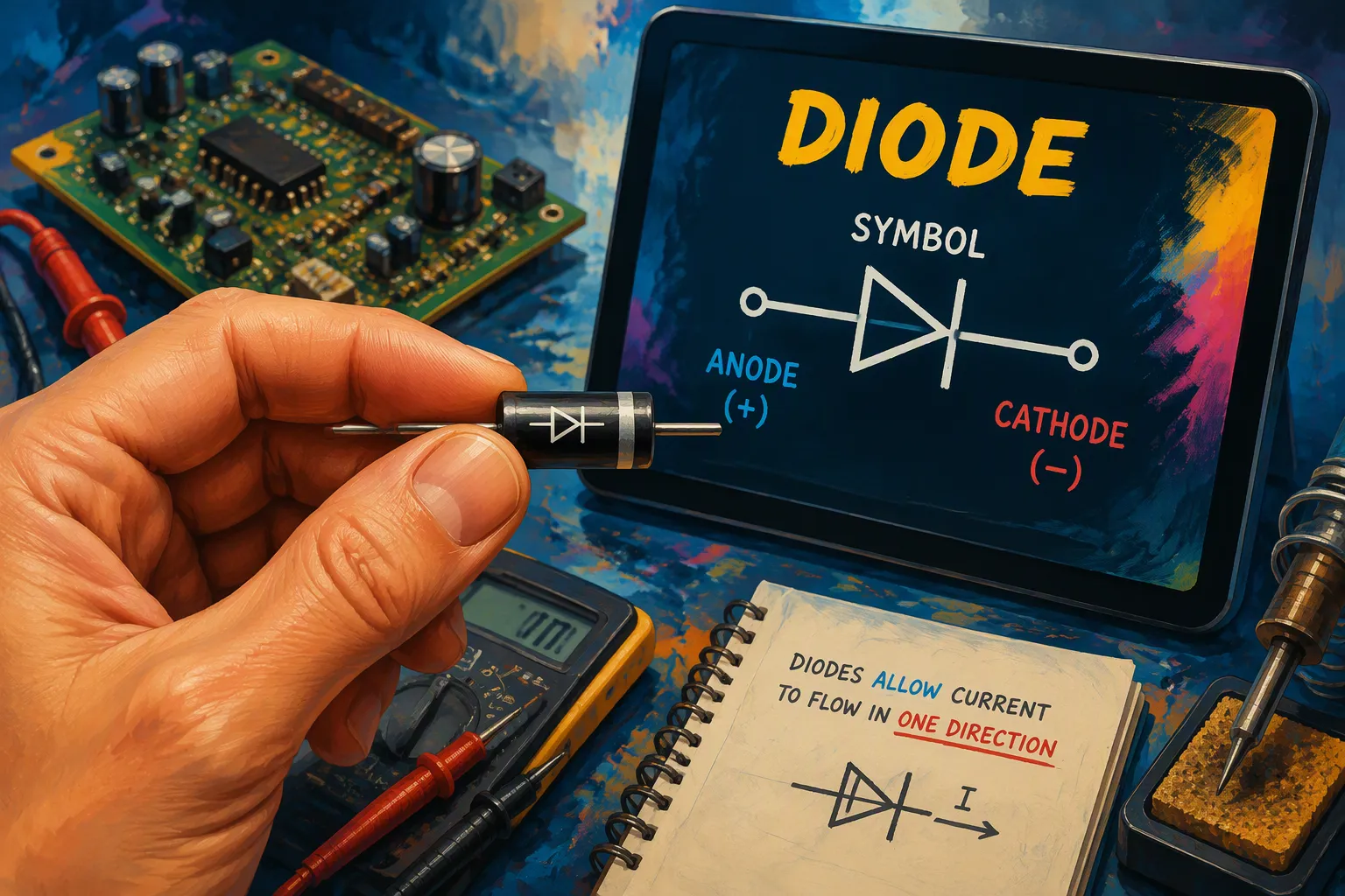
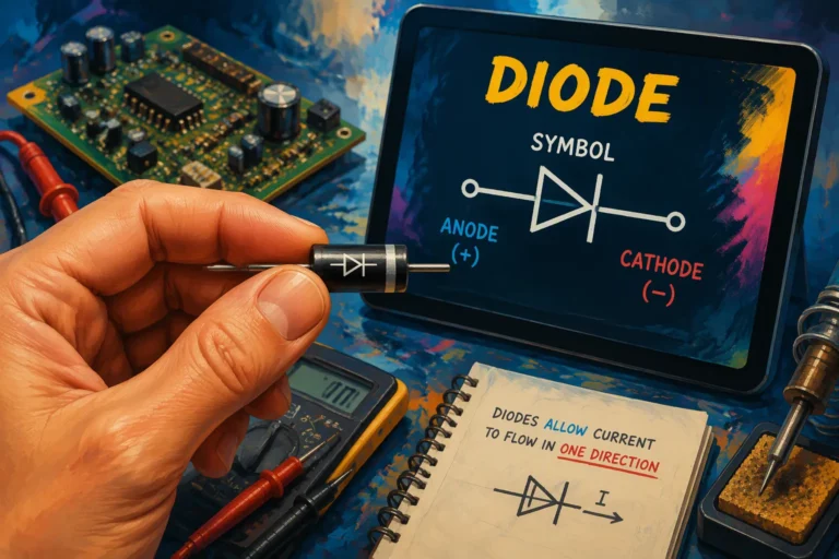
The diode symbol is a triangle pointing to a vertical line. The triangle shows the anode, and the line shows the cathode. Regular current flows from the anode to the cathode. This symbol stands for a two-terminal part called a semiconductor diode. Knowing the cathode line helps you read any circuit. You can match it to the stripe on a real diode. This simple symbol matters because reading the direction wrong causes failures. The worldwide discrete diode market will reach US$6 billion by 2030, which shows how important it is.
Key Takeaways
-
The diode symbol shows that current flows in one direction: from the anode (the flat edge of the triangle) to the cathode (the vertical bar).
-
You can find the cathode on a real diode by looking for the stripe or band, and check it with a multimeter.
-
Putting a diode in backward stops the flow of electricity and may harm your circuit, so always look at the symbol to see which way it points.
The Diode Symbol Shows Unidirectional Current Flow
The diode symbol teaches you one core rule: current moves in a single direction. The triangle points toward a thin bar. That thin bar depicts the cathode. The flat edge of the triangle is the diode’s anode. This setup makes current flow one way only. The IEC 60617 and IEEE 315-1975 standards both define this orientation, so every schematic you read follows the same convention.
Anode Arrow and Cathode Bar
The triangle works like an arrow. It shows you where conventional current goes. Current leaves the anode and travels toward the cathode. The thin bar at the tip blocks flow in the opposite direction. This is the heart of how a diode works.
The terminal entering the flat edge of the triangle represents the anode. Current flows in the direction that the triangle/arrow is pointing, but it can’t go the other way.
Actual electron flow moves opposite to the arrow. Electrons travel from the cathode back to the anode. Engineers still draw the electronic symbol with conventional current in mind. The direction of the arrow always tells you the forward direction.
Physical Markings and Multimeter Confirmation
A real diode carries a printed stripe or band. That line marking sits on the cathode side. The band matches the thin bar in the schematic. Texas Instruments’ 1N4001 teaching datasheet identifies the lead near its gray band as the cathode. You can trust this visual cue every time.
A multimeter confirms what your eyes see. Set the meter to diode test mode. Touch the red probe to one lead and the black probe to the other. A good silicon diode shows a forward voltage drop between 0.5 and 0.8 volts. Schottky diodes read 0.15 to 0.45 volts. Germanium types fall between 0.2 and 0.4 volts. LEDs display 1.5 to 3.5 volts.
Reverse the probes and the meter shows OL. No current flows. The probe arrangement that produces a normal reading tells you the polarity. The red probe sits on the anode and the black probe sits on the cathode. This simple test removes all doubt about an unmarked semiconductor diode.
Symbol Variations for Different Diodes

Common Symbol Variations and Typical Uses
Every diode keeps the same triangle and cathode bar. The bar changes shape to show what the part does. A Zener diode bends the bar like the letter Z. You connect a Zener in reverse bias, so its anode meets the negative supply. This part holds a steady voltage, and common breakdown values include 3.3, 5.1, 6.8, and 9.1 volts. Designers use it for voltage references, clamping, and input protection.
An LED adds two small arrows that point away from the triangle. Those arrows mean the part gives off light. A photodiode turns the arrows inward, because it takes in light instead. A Schottky diode puts small square bends at the ends of the bar. A varactor joins the standard electronic symbol with a capacitor at the cathode. If you ask what a diode variant does, look at the bar first. The bar always marks the cathode, and the triangle always shows current direction.
Quick-Reference Table of Diode Types
The table below compares symbols for some types of diodes. Use it as a fast lookup while you read a schematic.
|
Diode Type |
Symbol Difference |
Typical Use |
|---|---|---|
|
Rectifier |
Straight cathode line |
Rectification, protection |
|
Zener |
Bent bar shaped like a Z |
Voltage regulation, clamping |
|
LED |
Two outward arrows |
Indication, illumination |
|
Schottky |
Square bends at bar ends |
Low-loss switching |
|
Varactor |
Capacitor at the cathode |
Tuning, frequency control |
Reading the Diode Symbol in Real Circuits
Step-by-Step Method for Any Schematic
You can read any circuit diagram using a simple four-step method. First, find the cathode line. The vertical bar marks the cathode side, and the flat triangle edge marks the anode. Second, follow the normal current flow. Current goes in at the anode, moves through the triangle, and comes out at the cathode. Third, look for symbol changes. A bent bar means Zener, outward arrows mean LED, and square bends mean Schottky. Fourth, match the symbol to what the diode does. A rectifier handles basic one-way current flow, while a Zener controls voltage.
This method works because every diode symbol follows the same logic. The triangle always points in the forward direction. Some schematics use an arrow pointing toward a vertical line instead of a triangle, but the tracing idea stays the same. When you connect a diode, make sure current flows from the positive side to the negative side of the symbol.
Polarity Mistakes and Troubleshooting
PCB silkscreen markings help you put a diode in the right place. The stripe on a glass or plastic package matches the cathode line in the schematic. Manufacturers often copy this stripe on the silkscreen. Modern surface-mount diodes may use a notch or pin 1 mark instead. The clearest way puts the diode symbol right on the silkscreen. A simple line at the cathode or a K label also works. Stay away from unclear marks like plus and minus signs, because Zener and TVS diodes may not follow the same direction assumption.
A reversed diode causes real problems. No current flows, so an LED stays off. Diodes leak a small amount of current under reverse voltage. If reverse voltage gets high enough, the diode breaks down and conducts the wrong way. LEDs have a very low reverse voltage threshold. Past that limit, the LED turns power into heat instead of light, and that heat destroys it. Damage adds up over time, so short tests may hide the harm.
A multimeter confirms orientation. Turn off all power first. Set the meter to diode test mode. A good silicon diode shows 0.5V to 0.8V with the red lead on the anode. Reverse the leads and the meter reads OL. If both directions read the same, the diode is shorted. If both read OL, it is open. A reversed diode swaps these expected readings.
The cathode bar shows the negative side. The triangle points the way current flows. Every semiconductor diode uses this same pattern. If you misread the symbol, you reverse polarity and damage your circuit. Learning what a diode is begins with this visual language. Practice reading diode symbols on datasheets and real parts before you solder. This habit stops costly mistakes.
FAQ
How do you tell which side of a diode is the cathode?
Look for the vertical bar at the triangle tip. That bar marks the cathode. The flat triangle edge marks the anode. Current leaves the cathode and returns through the anode.
Why does the arrow direction matter when you place a diode?
The arrow shows forward current flow. You must match that direction to your circuit. A reversed diode blocks current and may damage the part.
Can you test a diode without a datasheet?
Yes. Use a multimeter in diode test mode. A normal reading appears in one probe arrangement only. That reading reveals the anode and cathode.