What is USB Pinout and Why Does It Matter
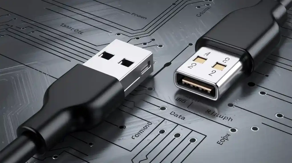
A USB pinout refers to the specific arrangement of pins in a USB connector that enables data and power transmission. This layout plays a pivotal role in ensuring seamless communication between devices. From charging your smartphone to transferring files between computers, USB technology underpins many everyday tasks. The global USB devices market, valued at $29.4 billion in 2023, is projected to reach $149.6 billion by 2032. Such widespread adoption highlights the critical importance of understanding USB pinouts for maintaining efficient connection and compatibility across devices.
Key Takeaways
- A USB pinout shows how pins are arranged in a USB plug. It is important for sending data and power.
- Knowing USB pinouts helps fix connection problems. It makes sure devices work well and smoothly.
- Different USB plugs, like USB-A, USB-B, and USB-C, have special pin setups for different uses.
- USB-C is the best plug. It sends data faster, gives more power, and can be plugged in either way easily.
- Learning about USB pinouts helps make custom cables and fix plugs. This improves how devices work.
What is a USB Pinout?
Definition and Basic Function
A USB pinout refers to the specific arrangement of pins within a USB connector. These pins serve as the backbone of USB technology, enabling both data transmission and power delivery between devices. Each pin in the configuration has a distinct role, such as transferring data, supplying power, or grounding the connection. For example, in a standard USB-A connector, the pinout includes four pins: one for power (VCC), two for data (D+ and D-), and one for ground (GND). This structured layout ensures that devices communicate efficiently and operate reliably.
Understanding the pinout is essential for maintaining device functionality. It allows you to troubleshoot issues like unrecognized devices or slow data transfer rates. Proper pin configurations also prevent potential damage caused by incorrect connections or inefficient power delivery. Whether you’re designing electronics or simply using USB devices, knowing the basics of a USB pinout can help you optimize performance and avoid common pitfalls.
How Does a USB Pinout Work?
The USB pinout works by creating a physical and electrical pathway for data and power to flow between devices. Each pin in the connector has a specific function, and together, they form a complete circuit. For instance, the VCC pin supplies +5V power, while the GND pin provides a 0V reference point, ensuring stable operation. The D+ and D- pins handle data transmission using differential signaling, a method that reduces interference and enhances signal integrity.
To better understand how a USB pinout works, consider the following table, which outlines the functions of pins in a USB-C connector:
| Pin | Function Description |
|---|---|
| A1, B12 | Ground connections providing a 0V reference point |
| A2, B11 | Active SuperSpeed data transmission from host to device |
| A3, B10 | Passive SuperSpeed data transmission from device to host |
| A4, B9 | Supplies +5V DC power |
| A5, B8 | Manages active communication for power delivery |
| A6, B7 | Actively manages positive data lines from host to device |
| A7, B6 | Passively transmits data from device to host |
| A8, B5 | Serves secondary bus lines for additional functionality |
| A9, B4 | Provides another source of +5V DC power |
| A10, B3 | Passively receives SuperSpeed data from device to host |
| A11, B2 | Actively receives SuperSpeed data from host to device |
| A12, B1 | Maintains stable 0V reference for reliable operation |
This intricate design allows USB to support various speeds and functionalities, from basic file transfers to high-speed data streaming. By understanding how a USB pinout works, you can better appreciate its role in ensuring reliable connectivity.
Key Components of USB Pinouts
The key components of a USB pinout include the pins themselves, their arrangement, and the electrical processes they facilitate. Each pin has a unique purpose, contributing to the overall functionality of the USB connection. Here’s a breakdown of the primary components:
- Power Pins: These include the VCC and GND pins, which supply power and establish a stable electrical circuit. For example, the VCC pin provides +5V, while the GND pin serves as the ground reference.
- Data Pins: The D+ and D- pins handle data transmission. They use differential signaling to minimize noise and ensure accurate data transfer.
- Identification Pins: In connectors like Micro-USB and USB-C, ID pins help identify the type of device connected and its capabilities.
- Additional Pins: Advanced connectors like USB-C include extra pins for features like SuperSpeed data transfer, power delivery negotiation, and alternate modes.
To illustrate, the USB-A pinout consists of four pins, each with a specific role:
| Pin | Name | Description |
|---|---|---|
| 1 | VCC | Power supply pin providing +5V |
| 2 | D- | Data Minus pin for transmission |
| 3 | D+ | Data Plus pin for transmission |
| 4 | GND | Ground pin for electrical circuit |
These components work together to enable seamless communication and power exchange between devices. By understanding these elements, you can troubleshoot issues, design custom cables, or simply ensure your devices function as intended.
Types of USB Connectors and Their Pin Configurations
USB-A: The Standard Connector
USB-A is one of the most recognizable USB connector types. It features a rectangular design and is commonly used in host devices like computers, laptops, and chargers. The pin configuration for USB-A includes four pins: one for power (VCC), two for data transfer (D+ and D-), and one for ground (GND). This straightforward layout has made USB-A a reliable choice for basic data and power transmission.
One of the key features of USB-A is its backward compatibility. Devices with USB 3.x technology, for instance, use the same connector shape but include additional pins internally to support faster data transfer rates. These connectors are often color-coded blue to distinguish them from earlier versions. Despite its widespread use, USB-A lacks the versatility of newer designs, as it only supports insertion in one orientation.
USB-B: Common in Peripherals
USB-B connectors are typically found in peripheral devices such as printers, scanners, and external hard drives. Unlike USB-A, USB-B has a square shape with beveled edges, making it easy to identify. The standard USB-B pinout also includes four pins: VCC, D+, D-, and GND. This configuration ensures stable data and power connections for devices that require consistent performance.
While USB-B remains a staple in many peripherals, its usage has declined with the rise of more compact options like Micro-USB and USB-C. However, it still plays a vital role in industrial and professional settings where durability and reliability are paramount.
USB-C: The Modern Connector
USB-C represents the future of USB technology. Its sleek, reversible design eliminates the frustration of incorrect insertions, making it user-friendly and efficient. Unlike USB-A and USB-B, USB-C boasts a 24-pin configuration, enabling it to support a wide range of functionalities. These include high-speed data transfer, power delivery of up to 100 watts, and the ability to carry audio and video signals through a single cable.
The versatility of USB-C has made it the standard for modern devices, from smartphones and laptops to gaming consoles. It supports multiple protocols, such as Thunderbolt 3 and DisplayPort, enhancing its adaptability. Additionally, USB-C microphones and other accessories offer plug-and-play convenience, simplifying your experience while delivering superior performance.
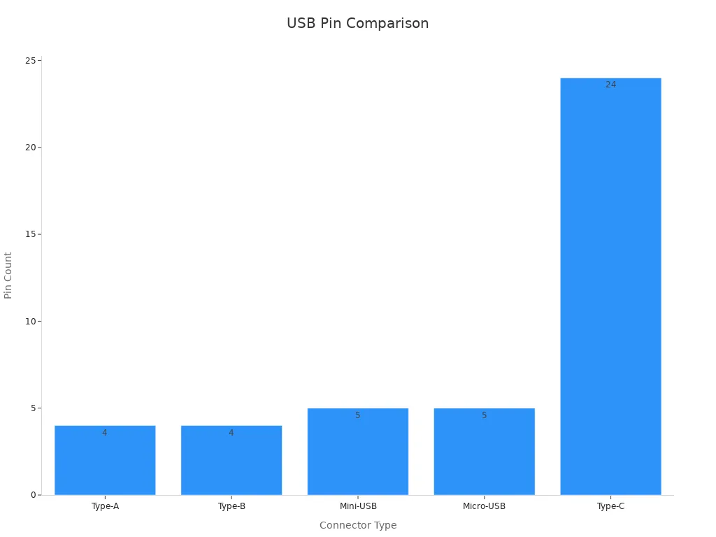
| Connector Type | Pin Configuration | Key Features |
|---|---|---|
| Type-A | 4 pins | Standard for host devices, blue for USB 3.x |
| Type-B | 4 pins | Standard for device connections |
| Mini-USB | 5 pins | Smaller form factor, GND moved to pin 5 |
| Micro-USB | 5 pins | Replaced Mini-USB, SuperSpeed version has extra pins |
| Type-C | 24 pins | Reversible design, supports multiple data and power configurations |
USB-C’s modern design ensures compatibility with future hardware, making it a future-proof solution for your connectivity needs. Its ability to handle multiple tasks simultaneously, such as charging and data transfer, sets it apart as the most versatile USB connector available today.
Micro-USB and Mini-USB: Compact Options
Micro-USB and Mini-USB connectors were designed to meet the growing demand for smaller, more portable devices. These compact options have played a significant role in mobile technology, offering reliable data transfer and charging capabilities.
Mini-USB, introduced earlier, was widely used in devices like digital cameras and MP3 players. Its five-pin configuration includes two pins for data (D+ and D-), one for power (VCC), one for ground (GND), and an additional ID pin for device identification. However, Mini-USB has largely been replaced by Micro-USB due to its bulkier design and lower durability.
Micro-USB, a slimmer and more efficient alternative, has become the standard for many smartphones, tablets, and other portable devices. Its design supports faster charging speeds and improved data transfer rates compared to Mini-USB. Additionally, Micro-USB connectors are available in versions that support USB 3, enabling higher efficiency and compatibility with modern devices.
Key Differences Between Micro-USB and Mini-USB:
- Mini-USB connectors are larger and limited to USB 2 speeds, making them less efficient.
- Micro-USB connectors are slimmer, more durable, and support USB 3 for enhanced performance.
- Micro-USB offers better charging capabilities, making it ideal for power-hungry devices.
Understanding the micro usb pinout is essential for troubleshooting and optimizing device performance. The pinout includes dedicated pins for power, data, and grounding, ensuring stable and efficient operation. Whether you’re designing custom cables or repairing devices, knowing the pinout can save time and prevent errors.
Key Features of USB Pinouts
Data Transmission and Differential Signaling
USB pinouts play a critical role in enabling efficient data transfer between devices. Differential signaling, a technique used in USB data transmission, ensures high-speed communication by reducing electromagnetic interference (EMI). This method uses paired data pins (D+ and D-) to transmit signals in opposite phases, canceling out noise and improving signal integrity. You benefit from faster and more reliable connections, especially when using USB-C for high-speed data transfer.
Differential signaling supports various data rates, ranging from Low Speed (1.5 Mb/s) to High Speed (480 Mb/s). The rise times for these rates vary, with High Speed offering the fastest edge rates at 100 ps. This versatility makes USB pinouts suitable for applications requiring stable and rapid data transmission.
| DATA RATES | RISE TIMES |
|---|---|
| Low Speed (LS) | 1.5 Mb/s |
| Full Speed (FS) | 12 Mb/s |
| High Speed (HS) | 480 Mb/s |
Differential signaling also addresses challenges like ground offsets and EMI. While it minimizes common-mode noise, it requires precise delay matching for optimal performance. This balance ensures that your USB connection remains robust, even in demanding environments.
Power Delivery and USB-PD Protocol
USB pinouts facilitate power delivery, a feature essential for modern devices. The USB Power Delivery (USB-PD) protocol revolutionizes how devices negotiate power requirements. With USB-C, you can enjoy up to 100W of power over a single cable, supporting multiple voltage options like 5V, 9V, 18V, and 20V. This flexibility allows devices to charge faster and operate more efficiently.
The USB-PD protocol enables bi-directional current flow, letting devices act as either a power source or sink. Smart negotiation ensures optimal voltage and current levels, preventing overcurrent events and enhancing safety. Fast Role Swap, a feature of USB-PD, allows devices to switch roles in under 150 microseconds during power loss, ensuring uninterrupted operation.
| Feature | Description |
|---|---|
| Maximum Power | Up to 100W over a single USB Type-C cable. |
| Voltage Options | Supports multiple voltages (5, 9, 18, or 20 V). |
| Current Flow | Bi-directional current flow allows devices to act as either source or sink. |
| Power Negotiation | Smart active negotiation of voltage and current. |
| Error Communication | Communicates errors such as overcurrent events. |
| Role Negotiation | Devices can negotiate their roles as source or sink dynamically. |
| Fast Role Swap | Allows quick role changes in under 150 microseconds during power loss. |
USB pinouts equipped with USB-PD ensure your devices receive the power they need while maintaining safety and efficiency.
Compatibility Across Devices and Standards
USB pinouts are designed to ensure compatibility across a wide range of devices and standards. Whether you’re using USB 2.0, USB 3.2, or USB4®, the pinout configuration supports seamless interoperability. Compliance tests confirm that USB devices meet essential criteria, such as system boot functionality, power transitions, and alternate mode negotiation.
| USB Standard | Tests Available |
|---|---|
| USB4® | PHY Electrical Compliance, CV/Functional, Interoperability, DP Tunneling, Compliance testing for all legacy USB versions |
| USB 3.2 | PHY Electrical Compliance, CV/Functional, Interoperability, Link Layer, Compliance testing for all legacy USB versions |
| USB 2.0 | PHY Electrical Compliance, CV/Functional, Interoperability |
Compatibility testing ensures that your USB connection supports device enumeration, selective suspend transitions, and charging with USB-C. These features make USB pinouts indispensable for maintaining reliable connections across diverse devices.
Tip: Understanding USB pinouts helps you troubleshoot compatibility issues and optimize device performance.
Identifying the Pinouts and Their Importance

Role in Troubleshooting Connectivity Issues
Identifying the pinouts is essential when troubleshooting connectivity issues. USB pinouts act as the blueprint for understanding how data and power flow between devices. When a device fails to connect or experiences slow data transfer, examining the pinout can help pinpoint the problem. For instance, a damaged or misaligned pin may disrupt the connection, leading to errors or reduced functionality.
You can use pinout diagrams to verify whether the pins are functioning as intended. These diagrams provide a clear view of the pin configuration, allowing you to check for physical damage or improper alignment. If a USB device isn’t recognized by your computer, inspecting the data pins (D+ and D-) can reveal whether the issue lies in signal transmission. Similarly, power-related problems, such as insufficient charging, often stem from faults in the VCC or GND pins.
In real-world applications, USB pinouts simplify troubleshooting across industries. Home-based medical devices, for example, rely on USB connections for seamless data transfer. When these devices encounter connectivity issues, identifying the pinouts ensures quick resolution, enabling uninterrupted health monitoring and analysis. By understanding the pinout, you can save time and prevent costly repairs.
Importance in Device Design and Manufacturing
Proper USB pin configurations are critical in device design and manufacturing. They ensure reliable data transfer, efficient power delivery, and compatibility across devices. As a designer, you must follow specific guidelines to optimize the performance of USB connections. For example:
- Position components to minimize the length of differential signal lines.
- Avoid exceeding two via pairs on a differential line pair.
- Keep connectors away from high-speed clocks and periodic signals to prevent signal degradation.
These practices preserve signal integrity and reduce interference, especially for high-speed USB standards like USB 3.2 and USB4®. Short differential signal lines minimize crosstalk, while impedance-controlled traces maintain stable data transmission. Maintaining a distance of at least 20 mils between signal and ground networks further reduces interference.
USB pinouts also play a vital role in manufacturing processes. They guide the placement of components and ensure compliance with industry standards. For example, USB technology is essential for communication and power delivery in modern electronics. Proper pin configurations guarantee that devices meet these requirements, enabling seamless operation in consumer and industrial settings.
Preventing Damage and Ensuring Functionality
Identifying the pinouts helps prevent damage and ensures functionality. USB connectors are designed to handle specific voltage and current levels. Misconfigured pins can lead to overcurrent events, overheating, or even permanent damage to your devices. By understanding the pinout, you can avoid these risks and maintain the longevity of your equipment.
For example, USB-C connectors support power delivery of up to 100 watts. This capability requires precise pin configurations to manage voltage and current flow. Smart negotiation features, such as Fast Role Swap, allow devices to switch roles during power loss, ensuring uninterrupted operation. Without proper pin alignment, these advanced features may fail, compromising the connection.
In organizational settings, USB pinouts enhance security measures. A mid-sized financial services firm implemented a structured USB port lockdown policy in 2024. This resulted in a 96% reduction in unauthorized USB connections and eliminated security incidents related to removable media. This case highlights the importance of identifying pinouts to optimize functionality and protect sensitive data.
By understanding USB pinouts, you can prevent damage, troubleshoot issues, and ensure your devices perform at their best. Whether you’re designing electronics or using USB devices daily, identifying the pinouts is a crucial step in maintaining reliable connections.
Practical Applications of USB Pinouts
Everyday Use in Charging and Data Transfer
USB pinouts are integral to your daily activities, especially for charging devices and transferring data. Whether you’re powering your smartphone or syncing files between your laptop and external storage, USB connections simplify these tasks. The structured pinout design ensures efficient power delivery and reliable data transfer, making USB technology indispensable.
Over the years, USB standards have evolved to meet growing power and performance demands. USB 1.0 and 2.0 deliver 5V and 500mA, ideal for small devices like single-cell Li-ion batteries. USB 3.0 increased the current limit to 900mA, addressing power shortages for larger gadgets. The Battery Charging Specification introduced in 2007 further enhanced charging speeds, allowing dedicated charger ports to deliver currents of 1,500mA and higher. These advancements ensure faster charging and seamless data transfer, even for power-hungry devices.
The versatility of USB pinouts extends to various devices, from smartphones and tablets to cameras and gaming consoles. By understanding the pinout configuration, you can optimize your connection for faster data transfer and efficient charging.
Role in Advanced Technologies
USB pinouts play a pivotal role in advanced technologies, particularly in projects requiring optimized power delivery and high-speed data transmission. Engineers and developers leverage USB pinouts to design systems that support modern protocols like USB Power Delivery (USB-PD). These configurations enable devices to negotiate power requirements dynamically, ensuring safe and efficient operation.
Several technical projects showcase the implementation of USB pinouts in cutting-edge applications. For example:
| Project Name | Description | Link |
|---|---|---|
| STM32G0C1E-EV Demonstrations | Demonstration projects for USB Power Delivery | Link |
| STM32G474E-EVAL Applications – USB-PD Consumer | Application for USB Power Delivery Consumer | Link |
| STM32L552E-EV Demonstrations | Demonstration projects for USB Power Delivery | Link |
These projects highlight the versatility of USB pinouts in supporting advanced functionalities like bi-directional power flow and high-speed data transfer. By understanding USB pinouts, you can explore their potential in innovative applications.
Custom Cable Design and Repairs
USB pinouts are essential for designing custom cables and repairing damaged connections. Whether you’re creating a specialized cable for a unique device or fixing a broken USB connector, knowing the pinout configuration ensures success. Each pin serves a specific purpose, from power delivery to data transmission, making accurate alignment crucial.
Custom cable design allows you to tailor USB connections to meet specific requirements. For instance, you might need a cable that supports both charging and data transfer for a high-powered device. By referencing the pinout, you can ensure the cable delivers optimal performance. Similarly, repairing a damaged USB connector involves identifying the affected pins and restoring their functionality. This process prevents further damage and extends the lifespan of your devices.
USB pinouts also enable hobbyists and professionals to innovate. You can experiment with alternate modes, such as using USB-C for audio or video transmission, by understanding the pin configuration. This knowledge empowers you to create solutions that enhance connectivity and functionality.
Understanding USB pinouts empowers you to optimize device performance and troubleshoot connectivity issues effectively. These pinouts form the backbone of USB technology, enabling seamless data transfer and efficient power delivery across devices. By mastering their configurations, you can prevent damage, enhance compatibility, and ensure reliable operation in everyday and advanced applications.
Take the time to explore USB pinouts further. This knowledge equips you to design custom solutions, repair connections, and unlock the full potential of your devices. Whether you’re a hobbyist or a professional, understanding USB pinouts ensures better connectivity and performance.
FAQ
What is the purpose of a USB pinout?
A USB pinout defines the arrangement of pins in a USB connector. These pins enable data transfer and power delivery between devices. Understanding the pinout ensures efficient communication and prevents connection issues.
How can I identify the pinout of a USB connector?
You can identify a USB pinout by referring to pinout diagrams or using a multimeter to test each pin’s function. These methods help you verify the roles of power, data, and ground pins.
Why is USB-C considered better than older USB types?
USB-C offers a reversible design, faster data transfer rates, and higher power delivery (up to 100W). It supports multiple protocols like Thunderbolt and DisplayPort, making it more versatile than USB-A or USB-B.
Can I repair a damaged USB connector?
Yes, you can repair a damaged USB connector by identifying the faulty pins and re-soldering them. Ensure you follow the correct pinout configuration to restore functionality and avoid further damage.
Are USB pinouts the same across all USB types?
No, USB pinouts vary by connector type. For example, USB-A has four pins, while USB-C includes 24 pins. Each type supports different features, such as power delivery and data transfer speeds.
Tip: Always check the specific pinout diagram for your USB connector type to ensure compatibility.