 English
 Arabic
 Chinese (Simplified)
 Dutch
Dutch French
 German
 Italian
 Portuguese
 Russian
 Spanish

What are the biggest BGA assembly challenges, and how can you fix them? Solder bridging, weak joints, voids, head-in-pillow, warping, misalignment, and hidden joint failures can all be handled. The right process controls, design choices, and inspection methods turn these defects into problems you can prevent. This post pairs each common defect with its cause and a short, practical solution. It also shows where those solutions fit in the full assembly process. Look at this case data:
Case | Intervention | Metric | Before | After |
|---|---|---|---|---|
Industrial control PCBA | DFM analysis, reflow-profile optimization, step-up stencil design, 100% in-line X-ray inspection | BGA voiding | >5% | <2% |
Industrial control PCBA | Same intervention | First-pass yield | 65% | >98% |
You can get similar results with steady BGA assembly practices.
Key Takeaways
BGA defects have clear causes. You can prevent them with design reviews, stencil optimization, and reflow profiling. These steps raise yield above 98%.
X-ray inspection shows hidden BGA defects. Visual checks cannot see bridges, voids, or poor wetting. This step is very important.
Nitrogen reflow stops oxidation. It reduces voiding. Use a controlled heat profile for strong joints.
Careful rework saves BGA assemblies that failed. Baking, controlled heating, and X-ray checks make rework success repeatable.
BGA Assembly Challenges and Solutions: The Basics
What Is BGA and Why It Matters
A ball grid array (BGA) does not use leads around the edges. Instead, tiny solder balls cover the bottom of the package. Each ball sits on a copper pad and stays in place with tacky flux. During reflow, heat melts the balls. Surface tension lines up the package and keeps the right gap while the solder cools. That simple process decides whether hidden joints form correctly.
Why pick BGA over a quad flat pack (QFP)? Older QFPs put leads on all four sides. As pin counts go up, lead pitch shrinks, and bridging risk rises. BGA avoids that limit by using the whole bottom surface for connections. This design packs high pin density into a small footprint. It also shortens electrical paths. Shorter paths cut signal delay, inductance, and noise, which matters for high-speed circuits. The flat array of solder balls moves heat well, so processors, memory devices, and ASICs often use this package.
Why Hidden Joints Raise Assembly Risk
BGA connections sit under the package, and that changes how you inspect them. You cannot see most of them. An optical microscope can only check outer rows, and an endoscope reaches only a few inner rows. Those hidden bga solder balls need X-ray inspection. X-ray sees through the package and shows voids, bridging, and poor wetting that no visual check can catch.
Top-down viewing has another weakness. The chart below shows how inspection effectiveness drops for features like heel fillets, side wetting, and lead coplanarity.
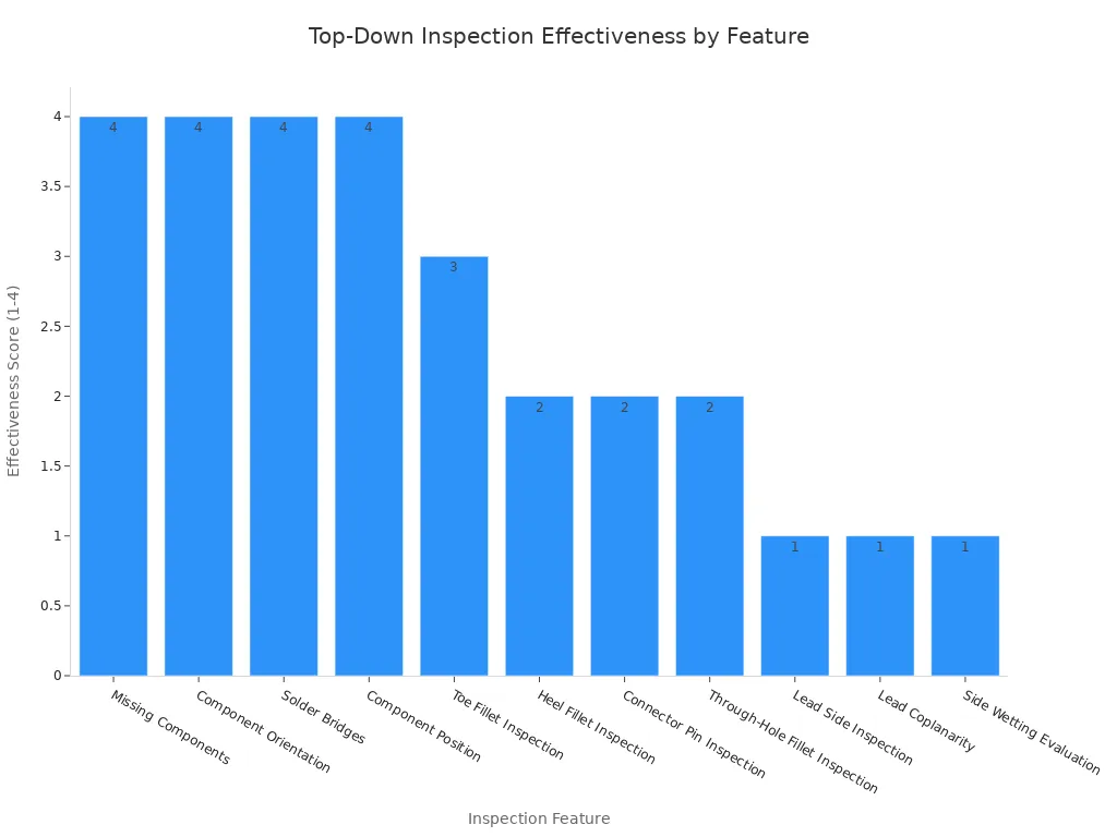
A joint can look fine from above and still hide a crack or a missing fillet. That hidden defect may weaken mechanical strength, shorten product life, or fail in the field. For this reason, X-ray inspection is not optional in any serious bga assembly; it is the main line of defense. Get this baseline right, and the specific defect solutions that follow become much easier for you to apply.
Common BGA Assembly Challenges and Fixes
Bridging, Insufficient Joints, and Voids
Solder bridging occurs when too much paste, stencil openings that are too big, or misaligned placement lets nearby pads join during reflow. You can solve this with stencil design and reflow profiling. In fine-pitch BGA assembly, thick foils hold extra paste in 0.5 mm pitch zones. Switching to stepped thinner areas fixes bridging. Tailored openings also control volume precisely. These methods push first-pass yields above 98%.
Insufficient joints and low standoff come from too little paste or poor wetting. A thin stencil can starve large pads, so you step up locally to add volume. Reflow tuning matters too. Preheat enough to activate flux without drying it out. This stops solder wicking and voids while building proper joint height.
Voiding in solder joints has several common causes for failure. Trapped flux gases, fast ramp rates, and moisture absorption all play a part. Via-in-pad filling solves the drain problem: an unfilled via can wick solder away and leave voids in the joint. Specify a filled and capped via-in-pad construction with a solid copper cap. Keep the cap surface flat; dimples or bumps lift the stencil and break the gasket seal. For paste, choose low-voiding flux formulations, store it properly, and let it reach room temperature before use. Bake PCBs and components before reflow to remove moisture. Vacuum reflow can reduce BGA voiding substantially. Voiding over 25% of a joint’s area can impair electrical and thermal performance, so a tighter target below 10% works better for verified via-in-pad joints.
Head-in-Pillow, Warpage, and Misalignment
Head-in-pillow (HiP) happens when dynamic warpage lifts the ball or heavy oxidation stops coalescence. Coplanarity and placement accuracy issues drive this defect. Nitrogen reflow measurably prevents re-oxidation and improves wetting. Published production data shows a measurable reduction in total void area with N₂ compared with air reflow using identical paste and profile. Use nitrogen with a low oxygen level. Keep peak temperature below 260°C to avoid damaging components. Keep time above liquidus controlled so joints form fully. Ramp at about 1.5°C/s. Extend preheat to about 90 s to even out the board temperature. Cool slowly so joints solidify without added stress. These values balance melting, flux preservation, and warpage control.
Warpage disrupts uniform contact between balls and pads. Unequal thermal expansion prevents complete coalescence and creates opens after cooling. Preheat the entire assembly to reduce thermal shock. Use fixtures that apply gentle pressure during reflow. Follow documented procedures to verify warpage limits.
Misalignment causes partial connections or bridging because balls hide beneath the package. Calibrate pick-and-place equipment regularly. Use optical or split-vision alignment tools. Verify pad condition and apply fresh paste or flux dots when needed. Strong bga quality control at every step prevents these defects. With disciplined bga solutions, you protect solder joint reliability and avoid the most common causes for failure.
Double-Sided BGA Assembly and the Process Flow
DFM, Substrates, and Paste Printing
Do a DFM and DFA review first. This finds land pattern errors before they hurt your yield. Keep pin A1 in the same direction on all BGAs. Put similar pitch classes together. These rules make placement checks easier and cut misorientation defects. Add local fiducials at diagonal corners for BGAs with a pitch below 0.5 mm. Use these fiducial specs:
Fiducial Type | Pad Diameter | Mask Clearance | Placement Rule |
|---|---|---|---|
Global | Sized for the board | Cleared for the solder mask | Non-collinear positions near board corners |
Local | Sized for the component | Cleared around the pad | Diagonal positions at critical components |
In double-sided assembly, each side needs its own fiducials. Mirror placement makes the setup more consistent. The right surface finish for BGA also matters. A flat finish supports fine-pitch paste release. The finish choice also changes how reliable the joints are over many reflows.
Solder paste printing is next. For fine-pitch parts at 0.5 mm pitch and below, control stencil openings so nearby pads do not bridge. Use filled and flattened vias for via-in-pad under BGA thermal pads. This prevents solder wicking and voids.
Placement, Reflow, Inspection, and Underfill
Pick-and-place accuracy decides if double-sided BGAs align correctly. Modern SMT systems with vision-matching can place parts within ±0.05 mm. Even 0.1 mm misalignment can cause opens or shorts, so the safe offset is tight. These specs work for 0.5 mm pitch and smaller.
Reflow soldering comes next. Double-sided BGA assembly sends the board through reflow twice. The second-side reflow profile lowers thermal stress on the side already built. Still, the process must handle the extra heat load on bottom-side BGAs. This raises thermal stress and warpage. Dynamic warpage can increase sharply at peak reflow temperature. This causes head-in-pillow defects in BGAs. Warpage also hurts pick-and-place accuracy, causing placement errors over 100 µm on fine-pitch BGAs. Leftover mechanical stress makes solder joints wear out faster under thermal cycling.
For double-sided ball grid array (BGA) assembly, moisture sensitive devices must bake before reflow. This removes absorbed moisture and stops popcorning. After reflow soldering, automated X-ray inspection checks hidden joints. This bga quality control step finds voids, bridging, and poor wetting. The underfill adds mechanical support. It lowers stress on solder balls during thermal cycling.
Rework and reballing happen last. Reballing fixes failed BGA parts by replacing solder balls on the package. It needs exact heat control and skilled operators. These bga solutions keep double-sided BGA boards dependable. Strong bga quality control at every step prevents the most common bga assembly problems. By using careful double-sided assembly practices, you protect yield and long-term performance.
BGA Rework Process and Best Practices

A careful bga rework process can save a failed BGA. A good bga rework process also includes a plan for inspection. Rework needs exact control. BGA assembly challenges do not stop after the first reflow.
Design Rules, Thermal, and Testability
BGA layout decides whether you can fix a board. Leave a clear gap on all four sides and put test pads outside that area. This keeps bed-of-nails pressure from breaking hidden joints. A well-designed bga assembly lowers rework challenges later.
Apply thermal reliefs on mask-defined SMD pads connected to copper pour, but not on vias. Size the spokes to balance heat flow and current capacity. Add teardrops to support bga quality control.
Route fanout points away. Never put a test point under a BGA. Good fanout gives clean access.
Rework, Reballing, and Inspection Integration
Doing bga rework requires exact thermal management. Use a rework station with a top heater, bottom preheater, and rigid support. Build a board-specific profile: preheat, controlled rise, soak, reflow, controlled cooling. Common rework challenges include heat damage and pad lifting.
Moisture sensitive devices need pre-baking. Bake PBGA packages before rework. Store them in moisture-barrier bags with desiccants until use. This stops popcorning during bga rework.
Reballing brings a failed BGA back to life. Pick a stencil that matches ball diameter and pitch. Apply flux, align the stencil, and deposit solder balls. Reflow just above liquidus and cool slowly. This special bga rework skill replaces the whole ball array. Reballing is one form of bga rework.
During bga rework, hold the board steady until solder solidifies. Use a vacuum pickup tube to avoid tearing pads. Avoid too much top heating during bga rework. Hot air, IR, vapor phase, and laser systems all handle bga rework. These bga solutions keep rework effective.
Do post-rework x-ray verification after reflow. AXI checks joint shape, voiding, and alignment. Post-rework x-ray verification is not optional for bga rework. It finds hidden bridges and opens. Use automated x-ray inspection on every reworked assembly. This keeps bga quality control strong.
Careful process control can prevent and fix BGA defects. It is not luck. You now know key actions: DFM review, stencil and paste optimization, reflow profiling, X-ray/AXI inspection, underfill, and controlled bga rework. These steps improve yield and reliability.
Choose a PCB assembly partner with documented process controls. They should meet recognized quality-management and workmanship standards. Check production skills and X-ray inspection for hidden joints. Confirm bga rework and reballing know-how. Check production skills and X-ray depth. Strong bga rework skills are important. Ask about bga rework tools. Review bga rework profiles. Test bga rework traceability. Demand bga rework standards. Validate bga rework training. Audit bga rework records. Use these lessons, and you turn hidden joints into controlled results.
FAQ
How much voiding can you accept in BGA solder joints?
Voiding over 25% of a joint’s area can impair electrical and thermal performance, so it should be controlled. A lower target below 10% works better for verified via-in-pad joints. Nitrogen reflow reduces total void area compared with air reflow using the same paste and profile.
What causes head-in-pillow defects and how can you prevent them?
Dynamic warpage lifts the ball during reflow. Heavy oxidation stops the solder from joining together. Nitrogen reflow with a low-oxygen atmosphere stops re-oxidation. Keep the peak reflow temperature below 260°C and control time above liquidus. This profile also helps bga rework.
Why do you need X-ray inspection for BGAs?
BGA joints sit under the package. Visual checks can only reach the outer rows. X-ray shows voids, bridging, and poor wetting. Automated inspection also checks assemblies after bga rework. Every reworked board needs X-ray verification to make sure joints are solid.
When should you use bga rework?
Use bga rework when a component fails or needs reballing. Reballing replaces the solder balls on the package. A rework station needs a top heater, bottom preheater, and rigid support. Always check with post-rework X-ray. Good bga rework brings failed parts back to working condition.
How long should you bake moisture-sensitive BGAs before reflow?
Bake moisture-sensitive BGAs before bga rework to remove absorbed moisture. Store them in moisture-barrier bags until use. This stops popcorning during bga rework.