Prototype PCB assembly gives you a way to turn your electronic ideas into working models quickly and efficiently. As a beginner, you can use a prototype to test your design, check for errors, and make improvements before moving to mass production. Prototyping plays a key role in electronics development because it lets you spot design flaws early and avoid expensive changes later. You can benefit from rapid prototyping by getting your boards assembled fast, which means you can test, refine, and move your project forward without delay. This process streamlines communication between design and manufacturing teams, helping you bring your product to market faster.
Key Takeaways
- Prototype PCB assembly allows you to test and refine your designs before mass production, saving time and money.
- Early detection of design flaws through prototyping helps improve product quality and ensures compliance with safety standards.
- Choosing the right components and following design principles are crucial for creating reliable prototypes.
- Effective communication with manufacturers and stakeholders enhances the prototyping process and leads to better outcomes.
- Iterative prototyping encourages continuous feedback and improvements, helping you build confidence in your final product.
What Is Prototype PCB Assembly
Definition and Purpose
When you start working with electronics, you will often hear about prototype pcb assembly. This process takes your initial pcb design and turns it into a real, working printed circuit board. The main goal is to check if your design works as planned before you make many copies.
Prototype PCB assembly is a critical phase following the PCB design process, validating the design’s feasibility and identifying potential issues. During this phase, the manufacturer performs a comprehensive analysis of the board’s strengths and weaknesses, which serves as a reference for future versions.
A prototype is usually a simple version of your final product. It may not have all the extra features, but it must work well enough to test your ideas. You use this step to find and fix problems early.
Why Prototyping Is Important
Prototyping helps you avoid costly mistakes. When you build a prototype, you can test your pcb and see how it performs. This step lets you make changes before you spend money on mass production.
| Reason for Prototyping | Benefit to You |
|---|---|
| Detects design issues early | Saves time and money |
| Allows testing and improvement | Increases product quality |
| Provides a real example | Helps with communication and feedback |
| Checks compliance with standards | Ensures safety and reliability |
| Speeds up development | Gets your product to market faster |
PCB prototyping gives you a chance to learn and improve. You can see how your printed circuit board works in real life and make better decisions for your project.
Key Benefits for Beginners
If you are new to pcb assembly, starting with a prototype offers many advantages:
- Design validation: You can check if your pcb works as expected and fix errors before making more boards.
- Quality assurance: Testing your prototype helps you make sure your printed circuit boards meet your needs and work well.
- Cost-effectiveness: Finding mistakes early saves you money and prevents expensive problems later.
By using prototype pcb assembly, you gain confidence and skills. You learn how to spot issues, improve your design, and get ready for larger projects.
Prototype Preparation
Design Basics
When you start preparing your prototype, you need to focus on the basics of pcb design. Good design helps your pcb work as expected and makes assembly easier. You should follow some key principles to avoid common mistakes. The table below shows important rules for beginners:
| Principle | Description |
|---|---|
| Component Placement Rules | Start with connectors, power modules, and high-current components. Keep sensitive parts away from noisy circuits. |
| Trace Width and Spacing Rules | Trace width must support the required current, and spacing must prevent arcing or interference. |
| Via Usage Guidelines | Minimize vias in high-speed routes and use thermal vias to reduce overheating. |
| Grounding Rules | Solid ground planes improve signal integrity and reduce noise. |
| Consistent Spacing | Maintain consistent spacing between high-voltage and low-voltage traces. |
| Power Trace Thickness | Keep power traces thicker than signal traces. |
| Short Return Paths | Ensure return paths are short and direct. |
| Component Placement at Edges | Avoid placing components directly at board edges. |
By following these rules, you make your prototype more reliable and easier to test.
Component Selection
Choosing the right parts for your pcb is a key step in prototyping. You want to make sure each component fits your design and works well with your assembly process. Here are some tips to help you:
- Select components and footprints based on your design needs, thinking about how each part will function.
- Check if the parts are available and affordable.
- Make sure the components match your assembly method.
- Understand the specifications of each component, including electrical and physical characteristics.
- Choose components based on intended use, performance requirements, cost, and availability.
During the pcb design phase, leave enough space between components. This helps prevent overheating and interference, making your printed circuit board more reliable.
Manufacturer Choice
Picking the right manufacturer for your prototype can make a big difference. You want a partner who understands your needs and can deliver quality results quickly. The table below lists important factors to consider:
| Factor | Description |
|---|---|
| Technical Expertise | Make sure the manufacturer can handle complex designs, such as multilayer boards. |
| Production Speed | Fast-turn prototyping, ideally within 3-7 days, helps you meet tight deadlines. |
| Quality Certifications | Look for compliance with standards like ISO 9001 or IPC Class 2/3 to guarantee reliability. |
| Customer Support | Responsive communication and detailed feedback during prototyping can prevent costly errors. |
You should always check reviews and ask questions before choosing a manufacturer. This step helps you avoid delays and ensures your pcb prototype meets your expectations.
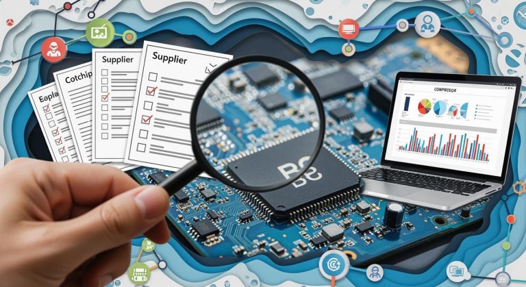
Sourcing Parts
Finding Components
You need to find the right parts for your prototype. Reliable sources help you avoid delays and problems with your pcb. Many companies offer strong strategies for sourcing components. The table below shows some trusted options:
| Company | Strategy |
|---|---|
| Siemens Manufacturing | Works with engineers and manufacturers to ensure reliable sourcing. |
| PCBONLINE | Keeps a large warehouse of common parts and controls quality through careful storage. |
| Technotronix | Offers customized solutions, including turnkey and mixed assembly for prototypes. |
You should check if the supplier has the parts you need for pcb prototyping. Make sure they can deliver quickly and provide quality components for your printed circuit boards.
Cost-Saving Tips
You can save money when sourcing parts for your prototype. Try these strategies:
- Use standard package sizes to get bulk pricing.
- Dual-source important components to prevent shortages and get discounts.
- Choose parts with long lifecycles to avoid redesign costs.
- Build strong relationships with suppliers for better prices.
- Look for alternative components that do the same job but cost less.
Tip: Always compare prices from different suppliers. This helps you find the best deal for your pcb.
Sourcing Mistakes
You must avoid common mistakes when sourcing parts for your prototype. These errors can cause delays and extra costs:
- Listing parts with internal nicknames instead of real orderable names.
- Missing or vague Manufacturer Part Numbers.
- Not including packaging details in your BOM.
- Using rare or obsolete parts from old designs.
- Relying on single-sourced ICs with long lead times.
- Not specifying voltage rating or package type.
- Ignoring standard footprints and values that distributors have.
You should double-check your BOM and make sure every part is clear and easy to order. This step helps your pcb assembly go smoothly and keeps your prototyping process on track.
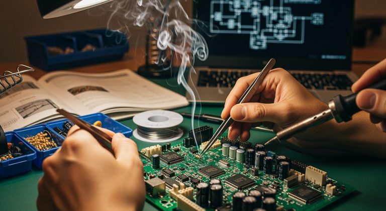
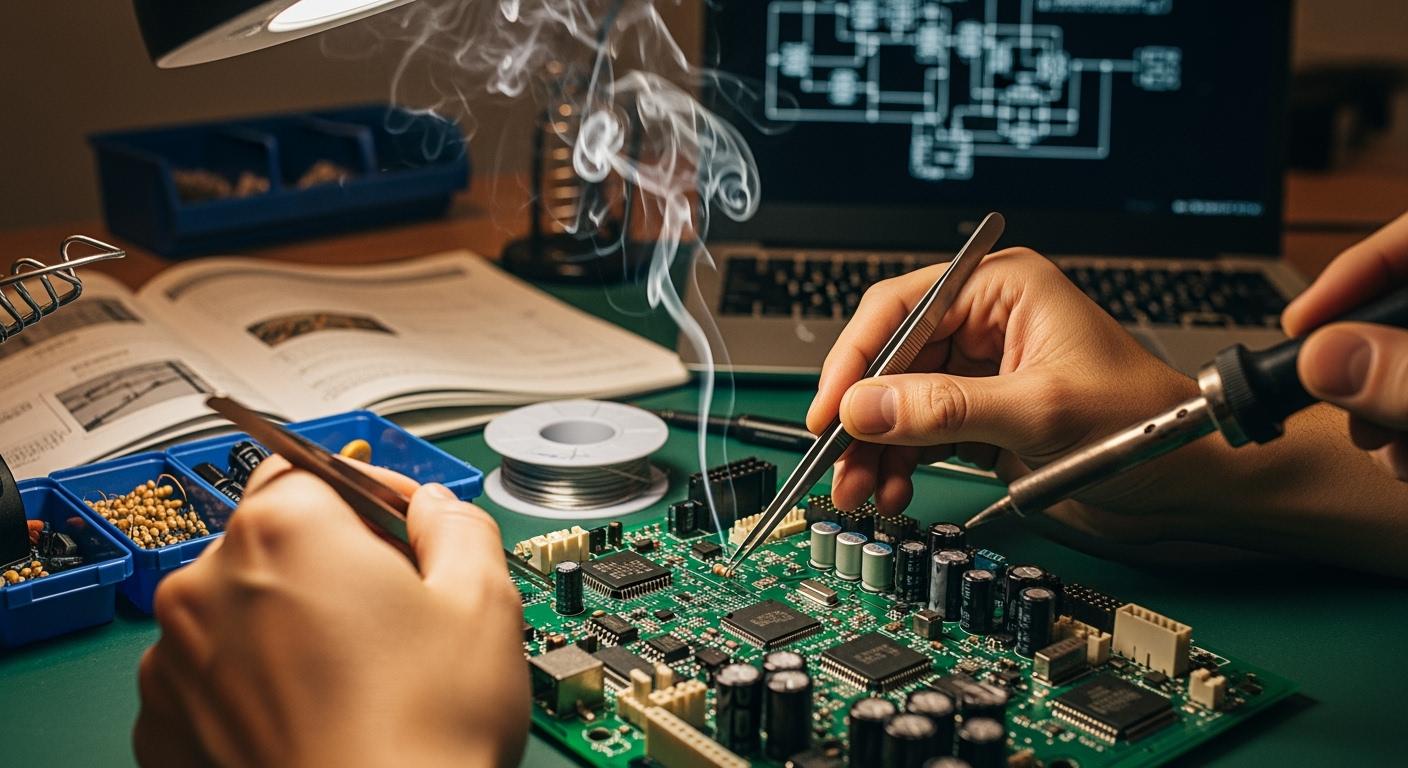
Prototype PCB Assembly Process
Understanding the prototype assembly process helps you turn your ideas into working electronics. You need to know how to choose between manual and automated methods, what tools to use, and the steps involved in building your prototype. This section will guide you through each part of the process, so you can approach pcb manufacturing with confidence.
Manual vs. Automated Methods
You can assemble your prototype using manual or automated techniques. Each method has its own strengths and best use cases. The table below compares these two approaches:
| Assembly Method | Best For | Key Advantages | Main Limitations |
|---|---|---|---|
| Manual Hand Soldering | R&D engineers, repair, quick one-off prototypes | Lowest cost setup, full control for rework | Time-consuming, inconsistent solder joints |
| Desktop Pick-and-Place + Reflow | Engineering teams, small batch production | Fast placement, higher accuracy | Higher equipment cost, setup needs calibration |
Manual hand soldering works well when you need to build a single prototype or make quick changes. You get full control over each pcb, which helps during early prototyping. Automated methods, like desktop pick-and-place machines and reflow ovens, speed up the process for small batches. These machines improve accuracy and consistency, which is important as your pcb fabrication needs grow.
King Field brings over 20 years of experience in both manual and automated assembly. You can rely on their expertise in Surface Mount Technology (SMT), through-hole assembly, and finished product assembly. Their advanced equipment supports both low-volume prototypes and larger production runs, making them a strong partner for any stage of your pcb manufacturing journey.
Essential Tools
You need the right tools for a successful prototype assembly process. The tools you choose depend on whether you use manual or automated methods.
For manual assembly, you should have:
- Soldering iron (variable power, fine tip)
- Solder wire (rosin-core or lead-free)
- Desoldering pump or wick
- Anti-static tweezers
- Magnifying glass
- Flux pen
- Anti-static wristband or mat
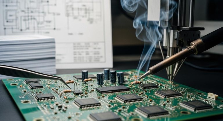
For automated assembly, you will need:
- Solder paste printer for even application
- Pick-and-place machine for precise component placement
- Reflow oven for strong solder joints
- Automated Optical Inspection (AOI) systems
- X-ray detectors for quality checks
Tip: Always use anti-static equipment to protect sensitive components during pcb assembly.
King Field uses advanced AOI and X-ray inspection tools at every stage of pcb manufacturing. Their quality assurance systems help you catch errors early and ensure your prototype meets high standards.
Step-by-Step Assembly
You can follow a clear sequence to complete your prototype assembly process. Each step builds on the last, guiding you from design to a finished, working printed circuit board.
- PCB Design and Fabrication
Start with schematic capture and pcb layout design. Check your design rules, generate Gerber files, and send them for pcb fabrication. - Component Procurement
Source all components, considering availability, lead times, and quality. Prepare your Bill of Materials (BOM) carefully. - Stencil Creation
Create a stencil for accurate solder paste application on your pcb. - Solder Paste Application
Apply solder paste to the pcb using the stencil. This step prepares the pads for component placement. - Component Placement
Place components on the pcb. Use tweezers for manual assembly or a pick-and-place machine for automated assembly. - Reflow Soldering
Heat the pcb in a reflow oven to form strong solder joints. For through-hole components, use wave soldering or hand soldering. - Inspection and Quality Control
Inspect the pcb for defects like solder bridges or misaligned parts. Use AOI and X-ray systems for thorough checks. - Through-Hole Component Installation
Insert and solder any through-hole components that remain. - Functional Testing
Test the assembled prototype against your design specifications. Make sure every function works as planned. - Iteration and Refinement
Review test results. Make improvements to your pcb design or assembly process as needed.
King Field offers full turnkey solutions for every step of the prototype assembly process. You can choose from full turnkey, partial turnkey, or commissioned pcb assembly services. Their flexible customization options let you tailor the process to your project’s needs, whether you need a single prototype or a small batch.
Note: A well-documented assembly process helps you avoid mistakes and speeds up future pcb manufacturing.
By following these steps, you gain hands-on experience with pcb fabrication and assembly. You learn how to manage each stage, from design to testing, and prepare for larger production runs. With the right tools and expert support, you can turn your prototype into a reliable, finished product.
Quality Control in Prototype Assembly
Quality control stands as a key part of successful prototype pcb assembly. You need to ensure that every pcb meets strict standards before moving to larger production. Careful inspection and adherence to industry requirements help you avoid costly mistakes and improve your pcb manufacturing process.
Inspection Methods
You can use several inspection methods to check the quality of your prototype pcb. Each method targets different types of defects in pcb fabrication and assembly. The table below shows the most effective inspection methods:
| Inspection Method | Description |
|---|---|
| Automated Optical Inspection (AOI) | Uses high-resolution cameras to detect surface defects like missing components and incorrect placements. |
| X-ray Inspection | Reveals hidden flaws in internal structures, useful for detecting voids in solder joints and BGA defects. |
| Manual Visual Inspection | Involves trained technicians spotting defects that automated systems might miss, such as subtle discoloration. |
King Field uses AOI for fast, accurate detection of surface defects and X-ray testing to find hidden issues in high-density pcb boards. You benefit from these advanced tools because they catch problems early in the pcb manufacturing process. Manual visual inspection adds another layer of quality, especially for subtle issues that machines might miss.
Tip: Start inspections early in the assembly process. Early detection prevents defects from spreading and saves time during prototyping.
Industry Standards
You must follow industry standards to ensure your prototype pcb meets reliability and safety requirements. These standards guide every step of pcb manufacturing and assembly. The table below lists important standards:
| Standard | Description |
|---|---|
| IPC | Standards for pcb assembly and manufacturing quality. |
| UL | Safety standards for electrical components. |
| ISO | International standards for quality management. |
Other key standards include:
- IATF 16949 for automotive pcb manufacturing.
- IPC-A-610 Class 3 for high-reliability electronic assemblies.
- IPC-6012 for pcb fabrication quality.
You should always check which standards apply to your project. Following these rules helps you build a prototype that performs well and passes future audits.
Regulatory Compliance
Regulatory compliance protects users and the environment. You need to use safe materials and keep detailed records during pcb fabrication and assembly. For example, RoHS compliance limits hazardous substances like lead, mercury, and cadmium in your pcb. The table below shows the maximum allowed concentrations:
| Substance | Maximum Concentration | Primary Concern |
|---|---|---|
| Lead (Pb) | 0.1% (1000 ppm) | Neurotoxin, environmental contamination |
| Mercury (Hg) | 0.1% (1000 ppm) | Severe toxicity to nervous system |
| Cadmium (Cd) | 0.01% (100 ppm) | Carcinogenic, kidney damage |
King Field uses RoHS-compliant materials in every prototype pcb assembly. This ensures your pcb manufacturing process meets global standards and supports access to markets in Europe, China, and California. In aerospace and medical device pcb fabrication, you must also follow standards like AS9100, FDA regulations, and ISO 13485 for full traceability and safety.
Note: Keep detailed records of inspections and materials. Good documentation helps you track quality trends and meet regulatory requirements during prototyping.
By following these inspection methods, industry standards, and compliance rules, you build a strong foundation for reliable prototype pcb assembly. You gain confidence in your pcb manufacturing process and prepare for successful scale-up.
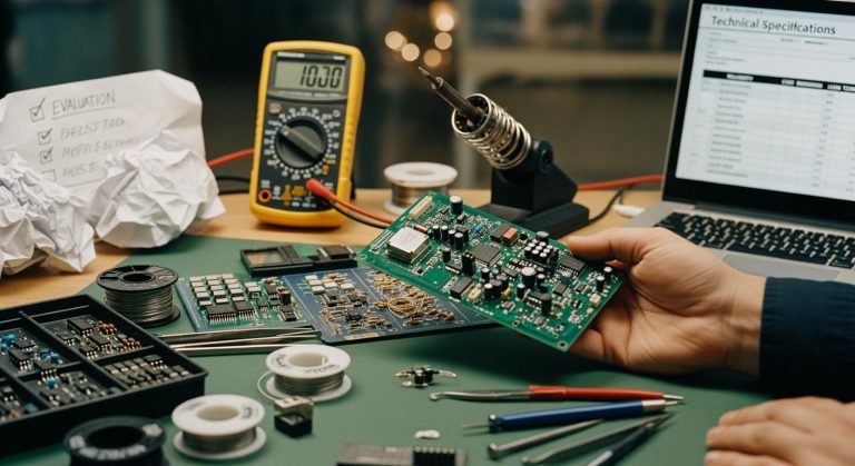
Prototype Testing and Debugging
Testing Importance
Testing plays a critical role in the prototype pcb assembly process. You need to test your pcb to find design weaknesses and confirm that each component works as expected. This step helps you check if your pcb maintains signal integrity and thermal stability. Testing also allows you to see if your design meets performance requirements and works reliably over time. When you test your prototype, you reduce uncertainty and gain confidence in your final product. Prototyping gives you a safe space to validate your ideas before moving to mass production. You can use these tests to make sure your functional prototypes are ready for the next stage.
Remember: Testing early and often helps you catch problems before they become expensive mistakes.
Basic Testing Methods
You have several methods to test your pcb during prototyping. Each method checks a different part of your design and helps you build a reliable prototype.
- Automated Optical Inspection (AOI) checks for missing or misplaced components on your pcb.
- Burn-In Testing runs your pcb for a long time to see if it can handle real-world use.
- X-Ray Inspection looks inside your pcb to find hidden problems, like bad solder joints.
- Functional Testing makes sure your pcb does what you designed it to do.
You can also use visual inspection, boundary scan, and in-circuit testing to find issues early. Thorough testing and debugging make sure your prototype works well before you move to production.
| Test Type | Description |
|---|---|
| Sinusoidal vibration test | Simulates repeated mechanical forces, often used for automotive or aerospace pcbs. |
| Random vibration test | Applies vibrations at different frequencies to mimic real-world conditions. |
| Shock testing | Checks if your pcb can survive sudden impacts or drops. |
Troubleshooting Tips
When you find a problem during testing, you need to troubleshoot your pcb. Experts recommend looking for common issues and using simple fixes. The table below shows some typical problems, their causes, and how you can solve them:
| Problem | Likely Cause | Fix |
|---|---|---|
| Solder bridges | Excess paste | Use a thinner stencil or less paste |
| Tombstoning | Uneven heating | Improve pad symmetry and heating |
| Cold joints | Low reflow temp | Check your oven profile |
| Part shift | Weak paste hold | Place components more precisely |
You should always check your pcb for these issues during prototyping. Careful troubleshooting helps you build a strong prototype and prepares you for larger production runs.
Iterative Prototyping
Feedback Collection
You need to collect feedback at every stage of your pcb project. Involving stakeholders early helps you spot problems before they grow. You can share your prototype with team members, engineers, or even potential users. Regular meetings give everyone a chance to see the pcb and share their thoughts. Simple tools like emails or group chats work well for sharing updates. When you encourage others to test your pcb, you get valuable input that helps you improve your prototype.
- Involve stakeholders from the start and keep them updated.
- Share your prototype at different stages to gather opinions.
- Plan meetings to show your pcb and ask for feedback.
- Use easy communication tools for updates.
- Let others test your pcb and suggest changes.
Design Improvements
You can use feedback to make your pcb better. Iterative prototyping means you build, test, and refine your prototype many times. This process helps you improve performance and reliability. When you listen to feedback from users, experts, and other stakeholders, you find areas that need work. Sharing your prototype at different stages lets you test new ideas and check usability.
- Refine your pcb design based on feedback.
- Involve stakeholders early to meet expectations.
- Share your prototype often for more input.
- Use a rapid cycle of design, build, test, and refine to reach the best results.
This approach helps you avoid costly mistakes and ensures your pcb meets all requirements.
When to Move Forward
You need to know when your prototype is ready for production. Check if your pcb meets all quality standards and design specifications. Make sure you have tested your pcb for function and performance. Use a clear plan for production testing, such as power rail checks, programming verification, and functional tests with jigs.
| Criteria | Description |
|---|---|
| Quality of Prototype | Your pcb must meet all standards and specifications for production. |
| Effectiveness of Testing | You should have a reliable testing process to verify your pcb works as planned. |
| Design Specifications | Your pcb must match every outlined design detail before moving to the next stage. |
If your pcb passes all tests and meets every requirement, you can move forward with confidence. This careful approach in prototyping helps you build a strong foundation for your final product.
From Prototype to Production
Preparing for Scale-Up
You need to prepare your pcb for mass production after successful prototyping. Start by defining your product goals and technical constraints. Create sample boards by fabricating 5–25 units. Test each prototype pcb assembly with functional, electrical, and environmental checks. Document every result, failure, and fix. If you find issues, redesign your pcb and repeat testing. When your printed circuit board passes all tests, transfer the final design to production. Make sure you hand over complete documentation for pcb manufacturing.
Careful preparation helps you avoid surprises during pcb fabrication and assembly. You build confidence in your design and ensure smooth transition to larger batches.
Assembly Expansion
Scaling up pcb manufacturing means expanding your assembly process. Evaluate your components and manufacturing methods to optimize performance and cost. Use automated assembly lines for higher efficiency. King Field supports both low-volume prototype pcb assembly and high-volume production. Their advanced equipment handles projects from a single pcb to over 10,000 units. You can rely on flexible customization options for different industries. King Field’s turnkey solutions cover everything from component sourcing to final testing and packaging.
- Automated assembly increases speed and consistency.
- Flexible customization meets unique project needs.
- Turnkey solutions simplify pcb fabrication and assembly.
Final Quality Checks
Before you launch mass production, perform final quality checks. Use In-Circuit Testing, Functional Testing, and Environmental Stress Testing to verify every pcb. King Field’s rigorous quality assurance process prevents failures and ensures high standards. Their team uses AOI and X-ray inspection at every stage of pcb manufacturing. You get reliable results and on-time delivery. Customer satisfaction remains a top priority.
| Quality Check | Purpose |
|---|---|
| In-Circuit Testing | Checks electrical connections |
| Functional Testing | Verifies design performance |
| Environmental Testing | Ensures durability and reliability |
Final inspections guarantee your pcb meets all requirements. You can move forward with confidence, knowing your assembly process delivers quality and reliability.
You have learned the essential steps for prototype pcb assembly. Start with a clear idea for your prototype. Design your pcb, select the right parts, and choose a reliable manufacturer. Build your pcb and test every prototype carefully. Prototyping helps you find mistakes and improve your pcb before mass production. Join online forums or local groups to share your pcb journey. Remember, every prototype teaches you something new. Do not fear mistakes. Each step in pcb prototyping builds your skills and confidence.
FAQ
What is the difference between prototype PCB assembly and mass production?
Prototype PCB assembly lets you build a small number of boards to test your design. Mass production creates thousands of boards after you finish testing. Prototyping helps you fix problems before you spend more money.
How long does prototype PCB assembly usually take?
You can expect most prototype PCB assemblies to take 3 to 7 days. The time depends on your design complexity, part availability, and the manufacturer’s schedule.
Can I assemble a prototype PCB by hand?
Yes, you can assemble simple prototype PCBs by hand using basic tools. Hand assembly works best for small projects or when you need to make quick changes.
What should I include in my Bill of Materials (BOM)?
You should list each component’s part number, value, package type, and manufacturer. Add quantity and any special notes. A clear BOM helps your assembly go smoothly.
Why is quality control important in prototype PCB assembly?
Quality control helps you catch errors early. You can use inspection tools to check for missing parts or bad solder joints. Good quality control gives you a reliable prototype and saves you time later.