Choosing the Right Actuator PCB for Your Project

Choosing the right actuator PCB is a critical step in ensuring the success of your project. It serves as the backbone of your system, enabling smooth communication between components and precise control of actuators. Selecting an unsuitable PCB can lead to inefficiencies, performance issues, or even system failures.
You should evaluate several factors, including compatibility with your actuator and system, functionality, cost, and performance. A well-matched actuator PCB not only enhances reliability but also optimizes operational efficiency. Making an informed choice saves time, reduces costs, and ensures your system performs as expected.
Key Takeaways
- Pick an actuator PCB that fits your project’s needs. Think about the type of actuator, environment, and what it must do.
- Check if the actuator and PCB work well together. Make sure the PCB can handle the actuator’s power and signals to avoid problems.
- Look at the price and quality of the PCB. Spending a bit more now might save money on repairs later.
- Test the PCB carefully before using it. Testing shows if it works well in real situations and meets your system’s needs.
- Choose a trusted company to make your actuator PCB. Check for certifications, ask for samples, and confirm they can meet your deadlines and design needs.
Understanding Actuator PCBs
What Is an Actuator PCB?
An actuator PCB (Printed Circuit Board) is a specialized electronic board that facilitates the control and operation of actuators within a system. It acts as the intermediary between the actuator and the control unit, ensuring precise communication and execution of commands. These PCBs are designed to handle specific electrical signals, enabling actuators to perform tasks such as movement, rotation, or force application.
To better understand actuator PCBs, consider their key performance metrics:
| Metric | Description |
|---|---|
| Force | Includes static and dynamic loads; static is the force when not in motion, while dynamic is during motion. |
| Speed | Measured primarily at no-load; decreases with increased load. |
| Energy Efficiency | Considerations include mass, volume, operating conditions, and durability. |
By evaluating these metrics, you can determine whether a particular actuator PCB meets your project’s requirements.
Importance of Actuator PCBs in Modern Systems
Actuator PCBs play a pivotal role in modern systems by ensuring seamless integration and operation of actuators. They enhance the efficiency and reliability of processes across various industries. Without a well-designed actuator PCB, your system may face issues such as signal interference, reduced performance, or even complete failure.
These PCBs also contribute to energy efficiency by optimizing power usage and minimizing waste. For example, in building automation systems, actuator PCBs enable precise control of HVAC systems, reducing energy consumption and operational costs. Their importance extends to safety-critical applications, where reliability is non-negotiable.
Common Applications of Actuator PCBs
Actuator PCBs are integral to numerous industries due to their versatility and functionality. Some of the most common applications of actuators and their PCBs include:
- Chemical, Oil, and Gas: Used for controlling valves and pumps in hazardous environments.
- Power Generation: Essential for turbine control and energy distribution systems.
- Aerospace: Critical for flight control systems and landing gear operations.
- Building Automation: Enable efficient control of lighting, HVAC, and security systems.
The global demand for fail-safe actuators, which rely heavily on actuator PCBs, was valued at USD 1.85 billion in 2024. This market is projected to grow at a steady rate of 7.5% CAGR, reaching USD 3.15 billion by 2033. This growth highlights the increasing reliance on actuator PCBs across industries.
How to Choose the Right Actuator PCB
Define Your Project Requirements
Defining your project requirements is the first step in selecting the right actuator PCB. Begin by identifying the specific functions and features your system demands. For example, does your project require precise control of actuator movements, such as linear motion or rotational motion? Consider environmental conditions like temperature, humidity, and exposure to corrosive elements. These factors directly impact the durability and reliability of the PCB.
Follow these guidelines to ensure your requirements are clear:
- Specify the type of actuators needed, such as linear actuators for linear motion or rotary actuators for rotational motion.
- Assess the compatibility of sensors and actuators with your system to meet accuracy and environmental needs.
- Choose robust components that can withstand harsh conditions and ensure long-term reliability.
By defining these parameters, you create a solid foundation for selecting an actuator PCB that aligns with your project goals.
Consider Compatibility with Actuator and System
Compatibility is a critical factor when choosing an actuator PCB. The PCB must seamlessly integrate with both the actuator and the overall system to ensure smooth operation. For instance, if your project involves motion control, the PCB should support the actuator’s specific movements, whether linear or rotary. Misalignment between the PCB and actuator can lead to inefficiencies or system failures.
To evaluate compatibility, examine the actuator’s technical specifications, including voltage, current, and signal requirements. Ensure the PCB can handle these parameters without compromising performance. Additionally, consider the system’s architecture. Does the PCB fit within the physical constraints of your design? Does it support the communication protocols used by your system? Addressing these questions helps you avoid costly redesigns and ensures optimal performance.
Evaluate Functionality and Features
The functionality and features of an actuator PCB determine its ability to meet your project’s demands. Advanced PCBs offer enhanced capabilities, such as improved signal processing, energy efficiency, and resistance to environmental stress. Evaluating these features ensures the PCB can handle the actuator’s tasks effectively.
Key performance metrics to consider include:
| Metric Type | Description |
|---|---|
| Dielectric Properties | Stability in humidity and low-loss laminates for high-frequency operations to prevent signal loss. |
| Thermal Properties | Matching coefficients of thermal expansion to prevent mechanical stress and modeling thermal gradients. |
| Mechanical Properties | Resistance to vibration, abrasion, and environmental corrosion through material selection. |
| Cost Efficiency | Balancing material availability and performance without over-engineering. |
For example, if your project involves actuators operating in extreme temperatures, prioritize PCBs with superior thermal properties. Similarly, for applications requiring high-frequency operations, choose PCBs with excellent dielectric properties to minimize signal loss. By focusing on these metrics, you ensure the PCB delivers reliable performance under varying conditions.
Assess Cost and Budget Constraints
Cost plays a significant role in selecting the right actuator PCB for your project. You need to ensure that the PCB meets your technical requirements without exceeding your budget. A well-planned cost analysis helps you balance performance and affordability, avoiding unnecessary expenses.
Start by developing a detailed project budget. This should include all potential costs, such as prototype development, parts procurement, manufacturing, and implementation. Maintaining an updated cost table can help you track expenses effectively. For example:
| Cost Category | Expected Cost | Actual Cost | Percent Uncertainty | Margin |
|---|---|---|---|---|
| Prototype Development | $500 | $520 | 5% | $20 |
| PCB Manufacturing | $1,200 | $1,150 | 4% | $50 |
| Parts and Implementation | $800 | $850 | 6% | $50 |
By including margins and contingency allocations, you can prepare for unexpected expenses. Additionally, performing a cost-benefit analysis allows you to evaluate the financial feasibility of different design and production options. This ensures that your actuator PCB delivers value for money while staying within budget.
Analyze Performance and Reliability
The performance and reliability of an actuator PCB directly impact the efficiency of your system. A reliable PCB ensures consistent operation, reducing the risk of downtime or failure. To assess these factors, you should consider both technical specifications and real-world performance data.
Reliability studies highlight the importance of robust PCB design. For instance, uneven conformal coatings on PCBs can lead to moisture ingress, causing voltage fluctuations in pressure sensors. This underscores the need for high-quality materials and precise manufacturing processes. Additionally, methodologies like the Arrhenius–Peck model can help predict corrosion mechanisms in humid environments, enabling you to select PCBs with enhanced durability.
You should also evaluate the PCB’s ability to handle environmental exposure. MEMS actuators, often sold as die, require joint reliability efforts to ensure long-term performance. Case studies, such as those on mirror actuators, provide valuable insights into failure modes and reliability approaches. By analyzing these factors, you can choose an actuator PCB that meets your system’s performance demands while minimizing the risk of failure.
Account for Environmental and Durability Needs
Actuator PCBs often operate in challenging environments, making durability a critical consideration. Industrial automation systems, for example, require PCBs that can withstand extreme heat, vibrations, and mechanical stress. Downtime in such systems can result in significant financial losses, emphasizing the need for reliable components.
Durability tests, such as fatigue and aging tests, provide insights into a PCB’s ability to endure harsh conditions. For instance:
| Test Type | Purpose |
|---|---|
| Fatigue Test | Simulates repeated mechanical stresses to evaluate long-term reliability. |
| Aging Test | Assesses performance under extreme temperature and humidity over extended periods. |
| Harsh Environment Test | Tests functional integrity in high-temperature and high-humidity conditions. |
By selecting PCBs that pass these tests, you ensure long-term fault-free operation. Engineers must also consider the specific environmental conditions of their projects. For example, PCBs used in outdoor applications may require additional protective coatings to prevent corrosion. Similarly, systems involving linear actuators or rotary motion control demand PCBs with superior mechanical properties to resist wear and tear.
Incorporating these considerations into your selection process helps you choose an actuator PCB that not only meets performance requirements but also withstands the rigors of its operating environment.
Types of Actuator PCBs and Their Applications
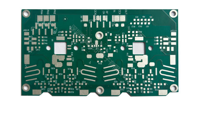
Single-Layer PCBs
Single-layer PCBs are the simplest type of printed circuit boards, consisting of a single conductive layer. These PCBs are ideal for straightforward systems that require basic functionality without complex circuitry. You might choose single-layer PCBs for projects where cost efficiency and quick production are priorities.
Advantages include lower manufacturing costs, simpler designs, and shorter lead times. These PCBs also support high-volume production, making them suitable for applications like consumer electronics or basic actuator systems. However, their simplicity limits their use in advanced systems. They offer slower speeds, lower operating capacity, and require larger dimensions to accommodate additional components.
For example, if your project involves types of actuators with minimal load capacity or basic motion control, single-layer PCBs can meet your needs. However, for cleanroom applications requiring ISO Class 3 standards, you may need to consider more advanced options due to their limited particle control capabilities.
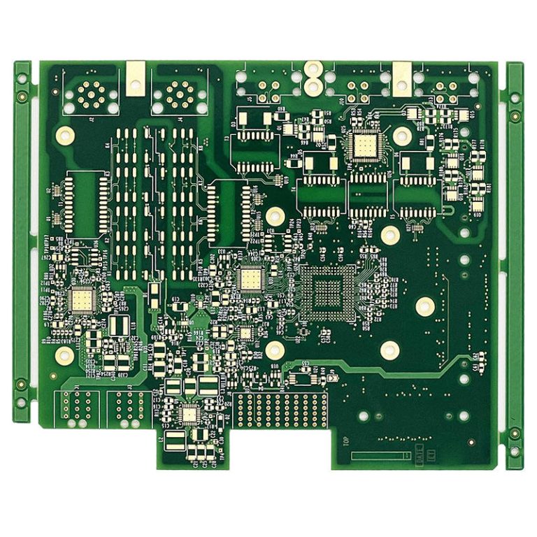
Multi-Layer PCBs
Multi-layer PCBs consist of multiple conductive layers stacked together, separated by insulating materials. These PCBs are designed for complex systems that demand higher performance and reliability. Their compact size and enhanced functionality make them suitable for applications like aerospace, medical devices, and advanced actuator systems.
Key benefits include smaller size, lower weight, and better quality. Multi-layer PCBs also offer improved durability and controlled impedance, which are essential for high-speed signals. For example, in systems requiring precise motion control, such as rotary actuators in robotics, these PCBs provide superior performance due to shorter signal travel distances and reduced resistance.
| Benefit | Description |
|---|---|
| Smaller Size | Compact design reduces space requirements. |
| Better Performance | Enhanced signal processing allows higher speeds and greater capacity. |
| EMI Shielding | Effective layer arrangement minimizes electromagnetic interference. |
| Improved Durability | Multiple layers enhance resistance to stress and environmental factors. |
If your project involves types of actuators operating in demanding environments, multi-layer PCBs ensure reliability and efficiency.
Flexible PCBs
Flexible PCBs are designed to bend and conform to various shapes, offering unmatched versatility for systems with space constraints or dynamic designs. These PCBs are ideal for applications requiring lightweight and adaptable solutions, such as wearable devices or compact actuator systems.
Flexibility metrics highlight their practicality. For instance, integrating ports upfront allows future adjustments, providing economic advantages under uncertainty. Flexible PCBs also support dynamic integration based on market feedback, making them suitable for unpredictable industries like semiconductors.
You might use flexible PCBs for types of actuators in systems requiring minimal adjustments or dynamic configurations. Their adaptability ensures compatibility with complex designs while maintaining performance. For example, in medical devices, flexible PCBs accommodate intricate layouts while meeting cleanroom standards like ISO Class 1,000 or Class 10,000.
Tip: When selecting flexible PCBs, consider their probabilistic NPV range to evaluate economic outcomes under varying conditions.
Rigid-Flex PCBs
Rigid-flex PCBs combine the durability of rigid boards with the adaptability of flexible circuits. These hybrid designs are ideal for integrated systems requiring compactness and reliability. By merging rigid and flexible layers, they enable seamless connections between components, reducing the need for connectors and cables. This design minimizes weight and enhances performance, making it a preferred choice for advanced applications.
Rigid-flex PCBs excel in industries like aerospace, medical devices, and consumer electronics. For instance:
| Application Type | Benefits Achieved |
|---|---|
| Aerospace | 30% weight reduction, improved reliability, simplified assembly |
| Medical Device | 50% volume reduction, enhanced biocompatibility, improved reliability |
| Consumer Electronics | 20% more battery capacity, improved drop test performance, reduced manufacturing time by 15% |
In automotive systems, rigid-flex PCBs provide durability and reliability under harsh conditions. They also enable sleek designs and foldable displays in consumer electronics. These features make them indispensable for types of actuators used in compact or space-constrained systems. For example, rotary actuators in robotics benefit from the reduced size and enhanced signal integrity offered by rigid-flex designs.
Tip: When designing with rigid-flex PCBs, consider the bending radius and stress points to ensure long-term reliability.
Custom PCBs for Specialized Applications
Custom PCBs cater to unique project requirements, offering tailored solutions for specialized applications. These PCBs are engineered to meet specific performance standards, making them essential for industries like automotive, aerospace, and medical devices. Specialty materials, such as high-temperature laminates or biocompatible substrates, ensure these PCBs perform reliably in demanding environments.
Custom PCBs find applications in high-power electronics, renewable energy systems, and telecommunications. For example, Highleap Electronics provides advanced PCBs for defense and renewable energy projects. In medical devices, custom PCBs meet stringent cleanroom standards while supporting intricate designs. Similarly, aerospace systems benefit from lightweight materials and enhanced durability.
You might choose custom PCBs for types of actuators requiring precise control or operating in extreme conditions. For instance, linear actuators in industrial automation demand PCBs with superior thermal properties to handle high loads. By tailoring the design, you can optimize the system’s performance and ensure long-term reliability.
Note: Collaborate with PCB manufacturers early in the design process to align specifications with your system’s requirements.
Step-by-Step Guide to Select Actuators and PCBs
Research Different Actuator Types (Pneumatic, Hydraulic, Electric)
Understanding actuator types is the first step in selecting actuators and PCBs for your system. Each actuator type offers unique advantages and is suited for specific applications. Pneumatic actuators excel in fast operations and hazardous environments. Hydraulic actuators deliver high force output, making them ideal for heavy machinery. Electric actuators provide precision control, making them a preferred choice for robotics and clean settings.
When evaluating actuator types, consider the following factors:
- Motion Requirements: Linear actuators are suitable for straight-line motion, while rotary actuators handle rotational tasks effectively.
- Force and Speed: Hydraulic actuators are best for high-force applications. Pneumatic actuators work well for moderate force and high-speed tasks. Electric actuators are ideal for precision tasks requiring controlled movements.
- Environmental Conditions: Pneumatic actuators perform reliably in hazardous environments. Hydraulic actuators withstand harsh conditions, while electric actuators thrive in clean and controlled settings.
- Power Source Compatibility: Match the actuator type with the available power source, such as compressed air for pneumatic actuators or electricity for electric actuators.
| Actuator Type | Key Features | Applications |
|---|---|---|
| Pneumatic | Fast operation | Packaging |
| Hydraulic | High force output | Heavy machinery |
| Electric | High precision | Robotics |
By researching actuator types thoroughly, you can identify the best fit for your system’s requirements.
Match Actuator Type with PCB Requirements
Matching actuator types with PCB requirements ensures seamless integration and optimal performance. Each actuator type demands specific PCB features to support its functionality. For example, electric actuators require PCBs with precise signal processing capabilities, while hydraulic actuators need robust PCBs to handle high power loads.
Follow these steps to align actuator types with PCB requirements:
- Evaluate Power and Signal Needs: Electric actuators demand PCBs with high-frequency signal processing and energy efficiency. Pneumatic actuators require PCBs capable of managing compressed air systems. Hydraulic actuators need PCBs designed for high-pressure operations.
- Consider Environmental Factors: Select PCBs with protective coatings for actuators operating in harsh conditions. For clean environments, prioritize PCBs with superior dielectric properties to prevent signal loss.
- Plan for Integration: Electric actuators integrate easily with electronic control systems, requiring PCBs with advanced communication protocols. Pneumatic and hydraulic actuators may need additional components for seamless integration.
| Specification | Electric Actuators | Pneumatic Actuators | Hydraulic Actuators |
|---|---|---|---|
| Speed | Moderate | Fast | Moderate |
| Force | Moderate | High | Very High |
| Control | Precise | Less precise | Moderate |
Matching actuator types with PCB requirements ensures your system operates efficiently and reliably.
Review Technical Specifications and Features
Reviewing technical specifications and features is crucial for selecting actuators and PCBs that meet your system’s demands. Start by analyzing performance metrics such as speed, force, and control precision. Compare these metrics across actuator types to identify the best option for your application.
Durability and reliability tests provide additional insights into actuator and PCB performance. Consider the following validation tests:
- In Vitro Tests: Assess reliability and safety under controlled conditions.
- Durability Assessments: Evaluate performance over multiple actuation cycles.
- Environmental Testing: Test functionality under extreme conditions, such as high temperatures or humidity.
- Mechanical Integrity Evaluations: Ensure robustness of joints and connections.
For actuators used in clinical applications, rigorous testing regimens like burst and leakage tests are essential. These tests determine maximum pressure limits and ensure long-term reliability. For example:
- Burst and leakage tests quantify actuator strength under high-pressure conditions.
- Block force measurements evaluate actuator output force.
- Durability tests simulate extended use to predict lifespan.
- Environmental tests mimic real-world conditions to ensure reliability.
| Test Type | Purpose |
|---|---|
| Burst and Leakage Tests | Determine maximum pressure limits. |
| Block Force Measurements | Quantify actuator strength. |
| Durability Tests | Simulate long-term use. |
| Environmental Tests | Evaluate functionality under physiological conditions. |
By reviewing technical specifications and conducting validation tests, you can select actuators and PCBs that deliver consistent performance and reliability.
Compare Costs and Value for Money
Cost analysis is a critical step in selecting the right actuator PCB. You need to ensure that the PCB delivers the required performance without exceeding your budget. Balancing cost and value involves evaluating both the upfront expenses and the long-term benefits of your choice.
Start by comparing the prices of different PCBs that meet your technical specifications. Look beyond the initial cost and consider factors like durability, energy efficiency, and maintenance requirements. A PCB with a slightly higher price tag may offer better reliability, reducing the need for frequent replacements or repairs. This can save you money over the lifespan of your system.
To make an informed decision, create a cost-benefit analysis. For example:
| PCB Option | Initial Cost | Lifespan (Years) | Maintenance Cost (Per Year) | Total Cost Over 5 Years |
|---|---|---|---|---|
| Option A | $50 | 3 | $10 | $100 |
| Option B | $70 | 5 | $5 | $95 |
In this scenario, Option B offers better value despite its higher initial cost. Its longer lifespan and lower maintenance expenses make it a more economical choice for your system.
Tip: Consider the scalability of your project. If your system is likely to expand, investing in a PCB with advanced features now can save you the cost of upgrading later.
Test and Validate the PCB for Your Application
Testing and validation are essential to ensure the PCB performs as expected in your specific application. Skipping this step can lead to costly failures or inefficiencies in your system.
Begin by conducting functional tests to verify that the PCB meets your design requirements. These tests should evaluate the PCB’s ability to handle the actuator’s power and signal demands. Environmental testing is equally important. Expose the PCB to conditions like extreme temperatures, humidity, and vibrations to assess its durability.
Validation protocols often include the following:
- Extended Lifespan and Reduced Maintenance Costs: A robust PCB design minimizes the need for frequent maintenance, which is especially important for systems like smart city devices with extensive sensor networks.
- Improved Product Quality and Performance: Rigorous testing ensures efficient operation, which is vital for applications like smart energy grids or public safety tools.
- Faster Development, Lower Costs: Design for Manufacturing and Assembly (DFMA) strategies streamline production, reducing both time and expenses.
For example, if your system involves actuators in outdoor environments, ensure the PCB passes harsh environment tests. These tests simulate real-world conditions, helping you identify potential failure points before deployment.
Note: Collaborate with testing labs or use in-house facilities to conduct these evaluations. Document the results to guide future design improvements.
Finalize and Source the Actuator PCB
Once you’ve tested and validated the PCB, the final step is sourcing it from a reliable manufacturer. Choosing the right supplier ensures you receive a high-quality product that meets your specifications.
When selecting a manufacturer, prioritize those with a proven track record in producing actuator PCBs. Look for certifications like ISO 9001, which indicate adherence to quality management standards. Request samples or prototypes to verify the PCB’s performance before placing a bulk order.
Consider the following checklist when finalizing your purchase:
- Lead Time: Ensure the manufacturer can deliver the PCBs within your project timeline.
- Customization Options: Verify that the supplier can accommodate any specific design requirements.
- After-Sales Support: Choose a manufacturer that offers technical support and warranty services.
- Scalability: Confirm the supplier’s capacity to handle larger orders if your system expands.
Tip: Establish a long-term partnership with a trusted supplier. This can streamline future projects and ensure consistent quality.
By following these steps, you can confidently select and source an actuator PCB that aligns with your project’s goals and budget.
Understanding actuator PCBs is essential for ensuring your system operates efficiently and reliably. These components play a critical role in integrating actuators and enabling precise control. When selecting an actuator PCB, focus on compatibility, functionality, cost, and durability. These factors directly impact the performance and longevity of your system.
Follow the step-by-step guide provided to make an informed decision. Testing and validation are crucial to avoid costly errors. If you encounter challenges, consult experts or manufacturers for tailored advice. This approach ensures your system meets its operational goals effectively.
FAQ
What is the most important factor when selecting an actuator PCB?
The most critical factor is compatibility. Ensure the PCB matches your actuator’s technical specifications, such as voltage, current, and signal requirements. Misalignment can lead to inefficiencies or system failures. Always verify the PCB integrates seamlessly with your system’s architecture.
Can I use a single-layer PCB for complex actuator systems?
Single-layer PCBs are not ideal for complex systems. They lack the capacity for advanced features and high-speed operations. For intricate designs, consider multi-layer or rigid-flex PCBs, which offer better performance, durability, and signal integrity.
How do I test an actuator PCB for reliability?
You can conduct environmental tests, such as exposing the PCB to extreme temperatures, humidity, and vibrations. Functional tests ensure the PCB handles power and signal demands effectively. Collaborate with testing labs or use in-house facilities to validate performance.
Are custom PCBs worth the investment?
Custom PCBs are worth it for specialized applications. They meet unique performance standards and environmental needs. For example, industries like aerospace and medical devices benefit from tailored designs that ensure reliability and efficiency under demanding conditions.
How do I ensure my actuator PCB supplier is reliable?
Look for manufacturers with certifications like ISO 9001. Request samples or prototypes to verify quality. Check their lead times, customization options, and after-sales support. Establishing a long-term partnership with a trusted supplier can streamline future projects.
Tip: Always review customer testimonials and case studies before finalizing a supplier.