How to Read Circuit Board Symbols for Absolute Beginners
Write a ‘How’ blog post on ‘How to read and interpret circuit board symbols effectively.’ Circuit board symbols are visual representations of electronic components, serving as a universal language in the world of electronics. They enable you to comprehend how circuits are structured and function. By mastering these symbols, you can identify components on a circuit board and understand their roles.
Learning to read schematics simplifies troubleshooting and repairs. For instance, schematics assist in pinpointing faults and damaged components. They also ensure accurate placement of parts during circuit board assembly, preventing costly errors. Furthermore, these symbols provide a detailed record of the design, facilitating future modifications to electronic systems.
Key Takeaways
- Circuit board symbols show parts of electronics, helping you learn circuits.
- Learn basic symbols like resistors, capacitors, and diodes to read diagrams easily.
- Keep a symbol chart handy to quickly recognise parts on circuit boards.
- Follow electricity paths in simple drawings to gain confidence and get better.
- Check online guides and datasheets often to understand circuit parts more.
Understanding Circuit Board Symbols
What are circuit board symbols?
Circuit board symbols are pictures that represent electronic parts. These symbols help engineers, technicians, and hobbyists share ideas easily. Each symbol stands for a specific part, like a resistor, capacitor, or diode. For instance, a zigzag line shows a resistor, and two straight lines mean a capacitor.
You’ll often see these symbols in circuit diagrams. These diagrams show how parts are connected and work together. By learning the symbols, you can understand a circuit’s design without seeing the actual parts.
Why are symbols used in schematics and PCBs?
Symbols are important for making schematics clear and simple. They make complex circuits easier to read by using standardised pictures for parts. Without symbols, diagrams would look messy and confusing.
To keep things consistent, organisations created rules for these symbols. For example, the IEC 60617 standard is used worldwide for electrical diagrams. In North America, the ANSI/IEEE 315-1975 standard influenced older documents. The ASME Y14.44-2008 standard works with IEEE 315 to organise part labels in schematics.
| Standard Name | Description |
|---|---|
| IEC 60617 | Global rules for symbols in electrical and electronic diagrams. |
| ANSI/IEEE 315-1975 | Older North American standard for schematic symbols, used in many older designs. |
| ASME Y14.44-2008 | Works with IEEE 315 to manage part labels in schematics. |
These rules make sure diagrams are easy to read and understand, no matter who makes or reads them.
How symbols simplify the process of reading electrical schematics
Symbols help you understand electrical schematics by breaking circuits into smaller parts. Instead of focusing on how parts look, you can focus on how they connect.
Imagine a circuit diagram with many parts. Without symbols, you’d have to figure out each part by hand, which takes a long time. Symbols save time by giving you a quick way to identify parts. A glance at the diagram shows what each part is and how it connects.
Using standard symbols also helps you spot patterns in circuits. Over time, you’ll notice common setups, like voltage dividers or amplifiers. These patterns make it easier to learn new schematics and fix problems.
Tip: Keep a symbol chart nearby when starting. It will help you learn and remember key electrical symbols.
Common Circuit Board Symbols and Their Functions
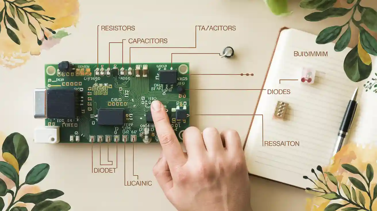
Knowing the symbols for basic circuit board parts is important. These symbols show the physical parts and explain how they work in a circuit. Here are three main symbols: resistors, capacitors, and diodes.
Resistor symbols and their purpose
A resistor symbol looks like a zigzag or a rectangle. Resistors slow down the flow of electricity in a circuit. In diagrams, they are labelled with names like “R1” or “R2.” These labels help you find specific resistors on a PCB. For example, R1 might be near the power source, while R2 could be part of a voltage divider.
Resistors are key to controlling electricity in circuits. Without them, delicate parts could break. When reading diagrams, check the labels to match the resistor symbol with the real part on the PCB.
Capacitor symbols and their purpose
Capacitor symbols have two types: straight and curved lines (polarised) or two straight lines (non-polarised). Capacitors store and release energy. They are used to filter, steady voltage, or connect signals between circuit parts.
In diagrams, capacitors are named “C1” or “C2.” These names help you find the right capacitor on the PCB. For example, C1 might filter power near the input, while C2 could steady a signal in the circuit.
Diode symbols and their purpose
The diode symbol is a triangle pointing to a line. Diodes let electricity flow in one direction only. They protect circuits from wrong voltage and change AC to DC in rectifiers.
Diodes in diagrams are labelled “D1” or “D2.” These labels help you locate the diode on the PCB. For instance, D1 might be a rectifier near the power input, while D2 could guard parts from voltage spikes.
Tip: Use the labels in diagrams to match symbols with real parts on the PCB. This makes fixing and building circuits easier.
Transistor symbols and their purpose
Transistors are very important in modern electronics. Their symbols show devices that boost signals or work as switches. There are two main types of transistors: bipolar junction transistors (BJTs) and field-effect transistors (FETs).
A BJT symbol has three parts: the emitter, base, and collector. The arrow on the emitter shows the current’s direction. For example, an NPN transistor has an arrow pointing out, while a PNP transistor has an arrow pointing in.
FET symbols look a bit different. They also have three parts: the source, gate, and drain. The symbol shows a line between the source and drain, with the gate nearby. Some FETs, like MOSFETs, have extra details, such as a dashed line for insulated gates.
Tip: Look at the arrow direction in transistor symbols. It shows how current moves through the transistor.
Transistors in diagrams are named “Q1”, “Q2”, and so on. These names help you find the transistor on the PCB. For example, Q1 might boost signals in an audio circuit, while Q2 could switch power in a supply.
Other essential symbols for beginners
When reading schematics, you’ll see other useful symbols. These include switches, LEDs, and integrated circuits (ICs).
- Switch symbols: Switches turn electricity on or off. Their symbols change depending on the type, like toggle switches or push buttons. A simple switch looks like a gap in a line, while a push button has a spring-like shape.
- LED symbols: Light-emitting diodes (LEDs) have a symbol like a diode but with arrows pointing outwards to show light. LEDs are labelled “D3”, “D4”, etc., and are used for lights or indicators.
- Integrated circuit symbols: ICs are complex parts with many functions. Their symbols are rectangles with pins on the sides. Each pin connects to a specific circuit part. ICs are named “U1”, “U2”, and so on.
| Symbol Type | What It Does | Example Label |
|---|---|---|
| Switch | Turns electricity on or off | SW1 |
| LED | Produces light | D3 |
| Integrated Circuit | Does many tasks in one component | U1 |
Note: Use a reference guide to learn these symbols faster. It will make reading schematics easier and save time.
How to Read and Interpret Circuit Board Symbols Effectively
Tips for recognising symbols in schematics
Learning to spot symbols in schematics gets easier with practice. Start by knowing the common ones like resistors, capacitors, and diodes. These symbols are often seen in diagrams and show how electricity moves in a circuit.
To get better, look for patterns in diagrams. For example, notice if a resistor is followed by a capacitor. Such patterns usually mean specific tasks, like filtering or controlling voltage. With time, you’ll read schematics faster and more easily.
Using diagrams with colours or labels can also help. Some diagrams split circuits into sections, like power supply or output. Keep a symbol chart close for quick help. This will make learning faster and reduce mistakes when reading diagrams.
Tip: Practise following electricity flow in simple diagrams. This helps you see how parts work together and prepares you for harder circuits.
Understanding the link between symbols and physical components
Each symbol in a diagram matches a real part on a circuit board. Knowing this link is key for fixing or building circuits. For example, a zigzag line means a resistor, and a triangle with a line shows a diode.
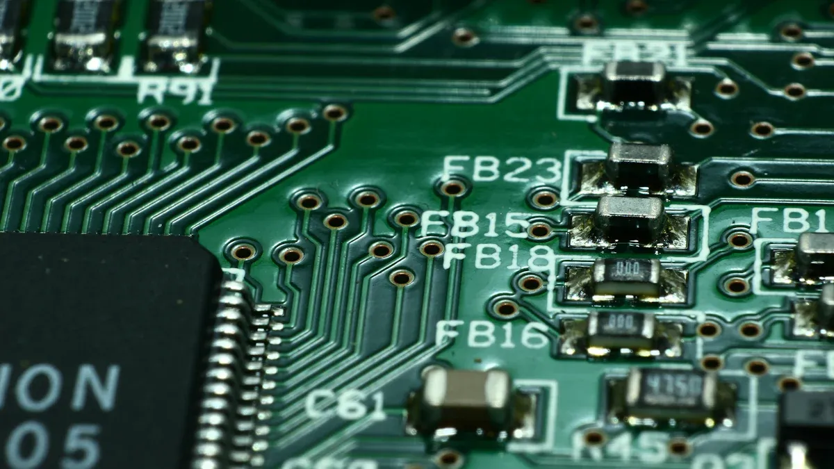
To connect symbols to parts, compare the diagram with the actual board. Find a symbol in the diagram, then locate its matching part on the board. Look at labels like R1, C2, or D3 to match them correctly.
Pay attention to how parts are placed. Some, like diodes and transistors, must face a certain way for electricity to flow. Diagrams often show arrows or marks for direction. On the board, look for similar marks, like a stripe on a diode or a flat side on a transistor.
Note: Handle boards gently to avoid breaking parts. Use a magnifying glass to see small labels or marks clearly.
Using reference guides to identify components on a PCB
Reference guides are great for finding parts on a printed circuit board (PCB). These guides include symbol charts, datasheets, and online tools that explain parts and their uses.
Start with a simple chart showing common symbols and their parts. Keep it nearby when working on schematics or PCBs. For more details, check the datasheet of a part. Datasheets give technical info, pin layouts, and how to use the part.
Online tools, like forums and tutorials, are also helpful. Many websites teach how to read schematics and find parts. Some even have interactive tools to practise matching symbols to real parts.
Tip: Save useful websites and organise datasheets on your computer. This will save time when you need quick info during circuit work.
By using these methods, you can easily read schematics and find parts on a PCB. This skill is important for tasks like fixing circuits, reading diagrams, and analysing circuits.
Practical Applications of Circuit Board Symbols
Steps to read electrical schematics
Reading schematics is easier with a clear method. First, look at the diagram’s layout. Find key areas like power supply, input, and output. These sections often have the main parts.
Next, check the symbols in the diagram. Spot familiar ones like resistors, capacitors, and diodes. Use a guide for symbols you don’t know. Look at how parts connect. Lines show wires, and dots mean wires join.
Trace the electricity flow in the circuit. Start at the power source and follow it to the output. This shows how the circuit works. Notice patterns like amplifiers or voltage dividers. These are common setups in diagrams.
Tip: Begin with simple diagrams before trying harder ones. This builds your confidence and skills.
Finding components on a PCB using symbols
To find parts on a PCB, compare the diagram with the board. Look for labels like R1, C2, or D3. These match the symbols in the diagram and help locate parts.
Check how parts are placed. Some, like diodes and transistors, have marks showing their direction. For example, a stripe on a diode shows the cathode. A flat side on a transistor shows its base.
Use a magnifying glass to see tiny labels and marks. Guides can also help you learn about parts. They explain what each part does and how it looks, making it easier to match them to the diagram.
Note: Be gentle with the PCB to avoid breaking small parts.
Using symbols to fix circuit problems
Symbols are key for fixing circuits. Start by studying the diagram to see how the circuit should work. Find important parts and their connections.
Look at the PCB for problems like burnt parts or broken lines. Use the diagram to find the problem area. Check the symbols to identify the parts involved.
Test the circuit with tools like a multimeter. Measure voltage, current, and resistance to find faults. Compare these readings to the diagram’s expected values. Replace damaged parts and test the circuit again.
Tip: Write down your steps while fixing circuits. This helps you learn and improve over time.
Learning circuit board symbols is important for beginners in electronics. These symbols are like a shared language, helping you understand diagrams and find parts on a PCB. Practising with schematics and real boards improves your confidence and skills. It might seem hard at first, but steady effort and patience bring success. Electronics is always changing, so keep learning whenever you can. Over time, reading and understanding symbols will feel easy and natural.
FAQ
What are circuit board symbols used for?
Circuit board symbols show electronic parts in diagrams. They explain how circuits work and help find parts on a PCB. Learning these symbols makes fixing, building, or understanding circuits easier.
How can you learn circuit board symbols quickly?
Use a chart with common symbols to start. Practise spotting them in simple diagrams. Online videos and tools can help you learn faster. Regular practice will make you better over time.
Why do some symbols look different in diagrams?
Symbols can vary because of different rules like IEC or ANSI. These rules may use slightly different designs for the same part. Knowing these differences helps you read diagrams from anywhere.
Can circuit board symbols help with troubleshooting?
Yes, symbols show which parts are linked to a problem. By following the diagram, you can find and fix broken parts. This makes solving issues quicker and easier.
Are circuit board symbols the same worldwide?
Most symbols follow global rules like IEC 60617. But older diagrams might use local rules. Learning common symbols helps you understand diagrams from around the world.
