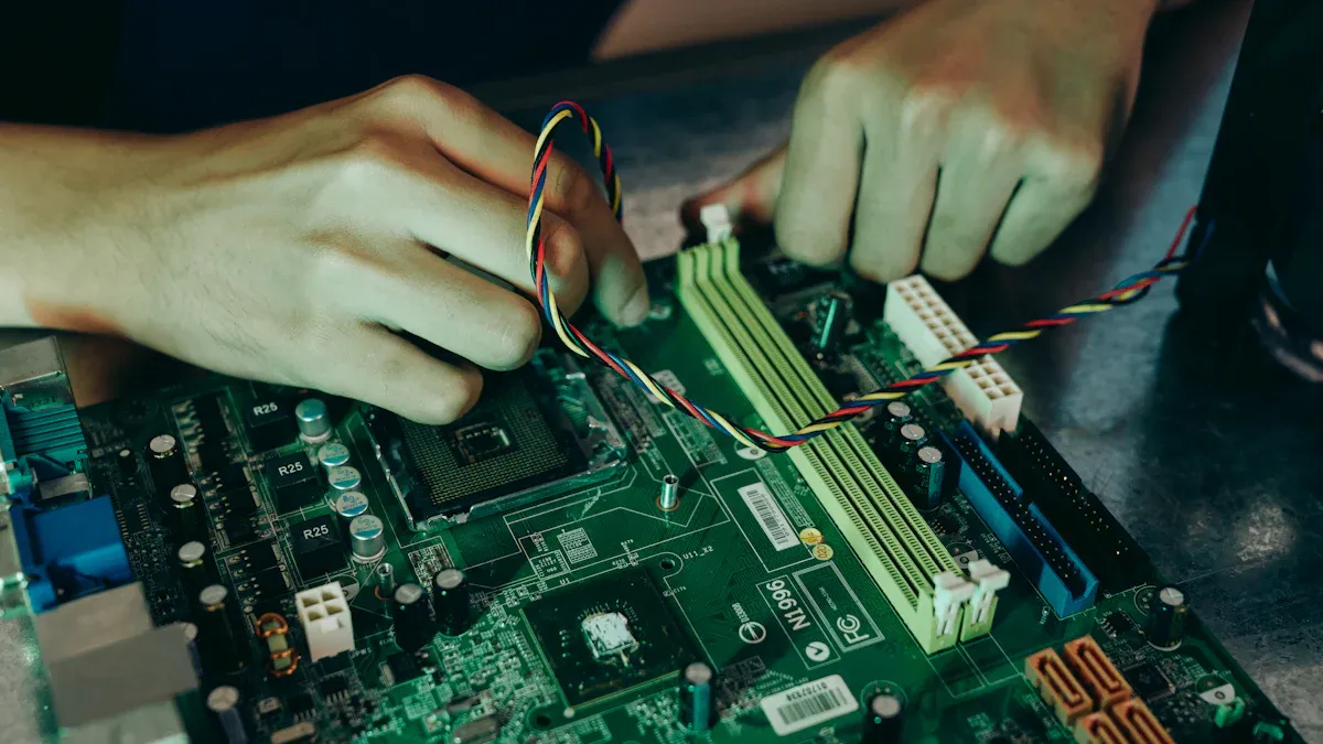
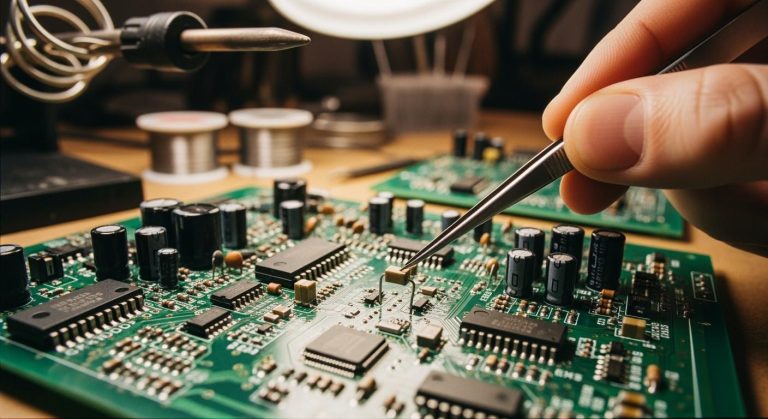
You often face PCB short circuit issues from manufacturing defects, design errors, environmental contamination, and component failures. These problems put your printed circuit boards at risk for device malfunction, overheating, and even fire hazards. The table below shows what can happen when a printed circuit board develops a short circuit:
| Consequence | Description |
|---|---|
| Device Malfunction | A short circuit disrupts the normal flow of current, leading to malfunctions or damage. |
| Overheating | Increased current flow can cause localized overheating, damaging components and posing fire risks. |
| Fire Hazard | In extreme cases, overheating may lead to fire hazards, endangering safety. |
If you want to avoid short circuits and keep your devices safe, you need to focus on PCB short circuit detection and prevention. You will learn how to spot signs of a pcb short circuit and use practical steps to prevent failures on your short circuits.
Key Takeaways
- Identify common causes of PCB short circuits, including manufacturing defects, design errors, and environmental factors. Understanding these helps you take preventive measures.
- Use visual inspections and multimeters to detect early signs of short circuits. Regular checks can save you from costly repairs and device failures.
- Follow best practices in PCB design, such as maintaining proper trace spacing and using quality materials. This reduces the risk of shorts and enhances reliability.
- Implement strict manufacturing controls and regular maintenance to ensure consistent quality. This proactive approach helps prevent short circuits and extends device lifespan.
- Utilize advanced tools like thermal cameras and X-ray inspection for effective short circuit detection. These tools help you find hidden issues that basic methods might miss.
Main Causes of PCB Short Circuit
Manufacturing and Assembly Issues
You often see pcb short circuit problems start during manufacturing and assembly. These issues can include design errors, material problems, and mistakes during component placement. The table below shows some of the most common causes of pcb short circuit that happen in mass production:
| Defect Type | Description |
|---|---|
| Design Errors | Incorrect trace widths or improper spacing can lead to shorts or signal integrity issues. |
| Material Issues | Low-quality substrates or inconsistent copper thickness can cause delamination or poor conductivity. |
| Manufacturing Mishaps | Misalignment during component placement or insufficient soldering can lead to connectivity issues. |
| Environmental Factors | Dust, humidity, or temperature fluctuations can introduce contaminants affecting soldering quality. |
Solder bridging and misaligned components can lead to short circuits on PCBs during assembly by creating unintended electrical connections between pads that should not be connected. This can occur due to various factors such as improper component placement, insufficient solder mask coverage, and incorrect solder paste application.
You may also encounter these problems:
- Poorly designed PCB with unequal weight distribution
- Lack of proper orientation of components
- Insufficient space between pads
- Incorrect settings of the reflow oven
- Inadequate placement pressure of components
These manufacturing and assembly issues are among the most typical causes of pcb damage. You need to pay close attention to these steps to reduce the risk of a pcb short circuit.
Design Errors and Clearance Problems
Many short circuits happen because of mistakes in pcb design. If you use inadequate trace spacing or incorrect pad sizes, you increase the risk of electrical arcing and crosstalk. These pcb design mistakes can cause board failures, especially in prototypes. You should always follow industry standards to minimize the risk of a pcb short circuit. Some important standards include:
- IPC-9592: Spacing requirements for high voltage devices.
- UL-61010-1: Safety requirements for electrical testing equipment.
- UL-60950-1: Standards for high and low-voltage applications.
You can also use these best practices in your pcb design:
- Maintain sufficient clearance between traces and vias to prevent shorts.
- Properly set pad spacing and line width to avoid shorts caused by design flaws.
- Control manufacturing tolerances to avoid issues.
- Implement impedance control for high-frequency designs.
- Optimize panelization for efficient manufacturing.
- Standardize component footprints for compatibility.
- Design for testability to reduce costs.
- Minimize the use of vias to reduce signal interference.
- Optimize power and ground layout by keeping traces short and thick.
If you ignore these guidelines, you may face problems such as electrical arcing, excessive heat buildup, and degraded signal quality. Using narrow spacing between traces is one of the most common causes of pcb short circuit, especially in high-power applications.
Component and Internal Faults
Component failures are another major source of pcb short circuit incidents. Some components, like capacitors and resistors, are more likely to fail and cause problems. The table below shows how different components can lead to short circuits:
| Component Type | Failure Cause | Impact on PCB |
|---|---|---|
| Capacitors | High failure rates under environmental influences, especially electrolytic. | Common cause of short circuits |
| Resistors | Can fail due to overheating or excessive current. | May lead to circuit failure |
| External Factors | Contamination, poor cleaning, and copper dendrite growth. | Causes short circuits |
You should also watch for poor cleaning, flux residues, and the accumulation of salts after exposure to water. Conductive dusts or metal shavings can settle on the board and create paths for a short circuit. Copper dendrite growth between closely-packed conductors is another hidden danger.
Internal faults in multilayer PCBs can be hard to spot. X-ray inspection helps you find hidden defects in internal layers, vias, and solder joints. Functional testing simulates real-world conditions and helps you identify failures under load. These methods help you catch problems before they cause a pcb short circuit in the field.
Environmental and Physical Damage
Environmental contamination is one of the leading causes of short circuits in industrial settings. When you dismantle waste electronic circuit boards, you release pollutants like polychlorinated biphenyls (PCBs) and polybrominated diphenyl ethers (PBDEs). These contaminants are common in places where electronic waste is processed.
Tin whiskers can also form on PCBs, especially when manufacturers use pure tin finishes to save costs. These tiny metal filaments can bridge gaps between conductors and cause a pcb short circuit. Physical damage, such as scratches or cracks, can expose copper traces and make it easier for moisture or dust to create a short circuit path.
You need to protect your boards from dust, humidity, and temperature changes. Regular cleaning and careful handling help prevent environmental and physical damage. By understanding these common causes of pcb short circuit, you can take steps to keep your devices safe and reliable.
PCB Short Circuit Detection and Prevention
Visual Inspection and Common Signs
You can often spot early signs of pcb short circuits by carefully inspecting your board. Visual inspection remains one of the first steps in pcb short circuit detection and prevention. Look for these common indicators:
| Visual Indicators of PCB Short Circuits | Description |
|---|---|
| Solder bridging or shorts | Excess solder connects two or more points, causing shorts. |
| Open circuits | Missing connections that can lead to malfunction. |
| Voids or bumps | Irregular solder shapes that affect connections. |
| Residual copper | Extra copper may create unwanted paths. |
| Insufficient solder | Too little solder leads to weak joints. |
| Excess solder | Too much solder increases the risk of shorts. |
| General quality of soldering | Clean, solid joints show good quality. |
| Shorts between conductors | Direct shorts can cause circuit failure. |
| Insufficient solder paste coverage | Weak connections and possible shorts. |
| Lifted and misplaced components | Poor seating can create shorts or open circuits. |
| Missing components | Missing parts can cause malfunction. |
| Contaminated solder paste | Poor solder joints and shorts. |
| Warpage issues | Board distortion can cause misalignment and shorts. |
Tip: Always check for these signs of pcb short circuits before powering up your board. Early detection helps you prevent short circuits and avoid costly repairs.
Electrical Testing and Multimeter Use
You can use a multimeter to detect short circuits quickly and accurately. This tool helps you confirm if two points on your pcb should connect or remain isolated. Follow these steps for effective pcb short circuit detection and prevention:
- Set your multimeter to continuity mode. The meter will beep if two points connect.
- Place one probe on the power trace or input pin.
- Place the other probe on the ground or a nearby trace you suspect.
- Listen for a beep. If you hear one where you should not, you have found a short circuit.
- Check resistance. Very low resistance between points that should not connect signals a short.
Electrical testing works well for surface issues, but it cannot always detect short circuits hidden inside multilayer boards. Manual visual inspection and automated optical inspection focus on surface defects. X-ray inspection, however, can reveal hidden problems that other methods miss.
| Method | Effectiveness for Identifying PCB Short Circuits |
|---|---|
| Manual Visual Inspection (MVI) | Limited to surface defects, cannot detect internal shorts |
| Automated Optical Inspection (AOI) | Focuses on surface defects, misses internal issues |
| X-ray Inspection | Specifically designed to detect hidden defects, including internal shorts |
Note: Electrical testing and visual inspection are essential, but you need advanced tools for detecting short circuits inside complex boards.
Advanced Tools for Short Circuit Detection
When you work with multilayer boards or complex assemblies, advanced tools help you detect short circuits that basic methods miss. These tools make pcb short circuit detection and prevention more reliable.
| Tool Type | Description | Price Range |
|---|---|---|
| Oscilloscopes | Show electrical signals over time, helping you spot noise and timing errors. | $300 – $2,000 |
| In-Circuit Testers | Test many points at once, checking for faults like shorts and opens. | $10,000 – $50,000 |
| Thermal Cameras | Find overheating spots that signal short circuits by visualizing heat. | $200 – $1,000+ |
| Logic Analyzers | Capture digital signals for debugging communication problems. | $100 – $1,000+ |
Thermal imaging can reduce your diagnostic time by up to 40% compared to manual testing. X-ray inspection improves defect detection rates by over 60% compared to optical methods alone. These tools help you find hidden shorts and improve your pcb short circuit detection and prevention process.
Pro Tip: Use in-circuit testing and thermal cameras to quickly locate hot spots and hidden faults in your board.
Prevent PCB Short Circuit with Design Best Practices
You can prevent pcb short circuit problems by following proven pcb design best practices. The IPC-2221 standard recommends several preventive design strategies:
- Electrical spacing and clearance: Maintain proper distances between traces and pads to prevent electrical arcing and short circuits, especially in high-voltage areas.
- Trace width and current carrying capacity: Calculate trace widths to handle the required current without overheating.
- Via design and placement: Follow rules for via size and location to ensure strong connections and avoid shorts.
Design rule checks (DRC) help you catch errors before manufacturing. DRC checks your pcb design for minimum spacing, trace widths, hole sizes, and clearances. This process helps you find problems early and prevent short circuits.
- Inadequate trace spacing increases the risk of shorts. Always enforce minimum spacing rules.
- One of the most frequent errors in pcb design is not leaving enough space between traces, pads, or vias. This can cause short circuits, especially in high-density layouts.
Remember: Preventive design strategies and regular DRC reviews are your best defense against short circuits.
Manufacturing Controls and Maintenance
You can further reduce the risk of pcb short circuit by using strict manufacturing controls and regular maintenance. Here are some best practices:
- Maintain consistent soldering temperatures and times for each component.
- Regularly calibrate and maintain soldering equipment.
- Use high-quality solder materials to avoid excessive flow or weak joints.
- Optimize soldering techniques for reliable joints and fewer short circuits.
- Ensure accurate component placement to prevent misalignment and solder bridging.
- Control humidity in the manufacturing area to prevent moisture absorption.
- Clean production equipment and work areas to reduce contamination.
- Use manual inspection and short circuit locator tools for effective detection.
Regular maintenance also plays a key role in pcb short circuit detection and prevention. You should:
- Inspect boards regularly to find potential issues before they cause failures.
- Clean boards to remove dust and residue that can lead to short circuits.
- Use proactive maintenance to keep your PCBs safe and reliable over time.
- Prevent overheating and signal loss with routine checks.
- Extend the lifespan of your devices through long-term maintenance.
Note: Combining manufacturing controls with regular maintenance ensures your boards stay reliable and helps you prevent short circuits in the long run.
By using these methods, you can master pcb short circuit detection and prevention. You will spot the signs of a short circuit early, use the right tools to detect short circuits, and apply preventive design strategies and best practices to keep your boards safe.
Tips for Locating Short Circuits
Step-by-Step Troubleshooting
You can use several methods to find a short circuit on your PCB. Start with a careful visual inspection. Look for solder bridges, stray copper traces, or burnt components. Use a magnifying glass or microscope to see small defects. If you spot cracked ICs or blown capacitors, you may have found the area with a short.
Here are some efficient methods to find a short circuit:
- Visual inspection for obvious shorts or unetched copper.
- Multimeter testing for continuity between traces.
- Thermal imaging to detect hotspots from excessive current.
- Checking for burnt or damaged components.
You should also use diagnostic tools to improve your troubleshooting process. The table below shows how professionals use different tools to locate short circuits:
| Diagnostic Tool | Purpose |
|---|---|
| Oscilloscope | Analyze signal integrity by observing waveforms for noise or distortion. |
| Thermal Camera | Identify hot spots caused by excessive current flow due to shorts. |
| LCR Meter | Test capacitors, inductors, and resistors for proper values. |
| X-Ray Inspection | Detect internal shorts or opens without damaging the board. |
| Microsectioning | Examine internal layers under a microscope (destructive method). |
| In-Circuit Testing (ICT) | Test individual components and connections for shorts and opens. |
| Automated Optical Inspection (AOI) | Scan for soldering defects and misalignments. |
| Functional Testing | Simulate real-world conditions to verify performance. |
| Environmental Stress Testing | Identify weaknesses by exposing the PCB to extreme conditions. |
Thermal imaging cameras work well when the PCB is powered on. They reveal hot spots that show excessive current flow. This method helps you pinpoint the exact location of a short circuit quickly.
Tip: Always power off the PCB and discharge capacitors before using a multimeter. This keeps you safe and protects your board.
Safe Repair Techniques
Once you finish locating short circuits, you need to repair them safely. Follow these steps:
- Set your multimeter to continuity mode.
- Power off the PCB and discharge any capacitors.
- Touch the probes to the points you want to test.
- Listen for the continuity beep or check for a near-zero resistance reading.
After confirming the short, remove excess solder or replace damaged components. Use a soldering iron with a fine tip for precise work. Clean the area with isopropyl alcohol to remove flux and debris. Inspect your repair with a magnifying glass to ensure you fixed the problem.
You should always follow best practices in pcb design to prevent future shorts. Keep traces spaced apart and avoid overcrowding components. These tips for locating short circuits help you maintain reliable boards and reduce failures. Use these methods to find a short circuit and keep your devices safe.
Troubleshooting and Repair for PCB Short Circuit
Systematic Fault Isolation
You need a clear plan when you start testing and troubleshooting a PCB short circuit. Begin by looking for visible problems like burnt components or bad soldering. Use a microscope to check for tiny solder bridges that might cause shorts. Here are some proven techniques you can use:
- Visual inspection: Examine the board for obvious solder bridges, burnt components, or damaged traces.
- Multimeter continuity check: Probe between power rails to confirm if a short exists.
- Divide and conquer: Disconnect sections of the board to narrow down the fault area.
- Thermal imaging: Scan the board for hot spots that reveal hidden shorts.
- Current injection method: Inject a small current and feel for heat to locate the short.
- Layer isolation: For multilayer boards, use the cut-trace method to isolate the problem section.
You can often find the source of a short circuit by following these steps. If you see burnt components, replace them before moving forward. Always document your process so you can track what you have checked.
Tip: Take photos of the board before and after each repair step. This helps you spot changes and avoid missing details.
Repair Tools and Safety
When you repair a PCB, you must use the right tools and follow safety rules. Soldering irons, multimeters, and thermal cameras are common tools for this job. Always protect yourself and your board during repairs. The table below lists important safety precautions:
| Safety Precaution | Description |
|---|---|
| Conduct soldering under exhaust hoods | Ventilates harmful fumes from soldering. |
| Monitor lead content in the air | Reduces exposure to heavy metals. |
| Clean surfaces with heavy metal wipes | Removes hazardous contamination. |
| Wear gloves when handling PCBs | Protects your skin from chemicals. |
| Disconnect power sources | Prevents electrical hazards. |
| Discharge capacitors | Avoids electric shock from stored energy. |
| Wear safety glasses | Shields your eyes from solder splatter. |
| Use grounded wrist straps | Prevents electrostatic discharge damage. |
| Wash hands before handling PCBs | Reduces contamination and future board failure. |
You should also:
- Make sure the equipment is unplugged and capacitors are discharged before you start.
- Wear safety glasses to protect your eyes from flying leads or solder.
- Use grounded wrist straps to prevent static electricity from damaging sensitive parts.
- Handle the board by its edges to avoid adding oils or dirt.
If you follow these steps, you lower the risk of injury and prevent further damage to your PCB. Careful soldering and proper safety habits help you fix shorts without creating new problems.
You improve device reliability and safety when you understand the causes of PCB short circuits.
- You identify external contamination, bad soldering, and design mistakes, which lets you take action early.
- Proactive steps help you reduce failures and keep your devices working longer.
- You ensure safe operation in many conditions.
Combining robust design, quality manufacturing, and regular maintenance gives you strong quality control. The table below shows how each step supports quality:
| Quality Assurance Measure | Description |
|---|---|
| Design for Manufacturing (DFM) Reviews | Identifies potential manufacturing challenges early in the design phase to prevent production issues. |
| Material Selection and Sourcing | High-quality substrates and components improve performance and durability. |
| Manufacturing Process Control | Standardized procedures reduce variability and improve consistency. |
| Final Inspection and Testing | Comprehensive testing verifies functionality and identifies defects before shipping. |
| Automated Optical Inspection (AOI) | Scans PCBs for surface defects, helping detect inconsistencies early in the process. |
| X-ray Inspection | Detects hidden defects in multilayer and high-density PCBs. |
| In-Circuit Testing (ICT) | Verifies electrical performance and identifies issues like short circuits. |
| Functional Testing | Simulates real-world conditions to validate PCB performance. |
| Environmental Stress Testing | Assesses durability under extreme conditions to predict performance in challenging environments. |
You see real results in high-reliability industries. For example, aerospace data recorders in France use high-precision boards with advanced processes and full inspection. The table below highlights their approach to quality:
| Element | Details |
|---|---|
| Customer’s Country/Region | France |
| Cooperation Period | July 2014 – Present |
| Customer’s Sub-field | Data Recorders |
| Scale of Cooperation | Primarily samples, hundreds of models ordered annually with extremely high repurchase rate |
| High-Precision Case | High TG 16-Layer Board |
| Advanced Processes | High Layer Count, BGA, Gold Fingers |
| Industry Application | Aerospace Data Recorder |
| Clear Requirements & Pain Points | Wide variety of models, low quantity required per model; High order frequency, requiring flexible cooperation; All PCBA boards incorporate BGAs, requiring high-quality soldering and guaranteed quality |
| Process Capability | Manufacturing processes for high multilayer boards (18+ layers), HDI, heavy copper, rigid-flex; Uses nitrogen reflow soldering, greatly improving soldering quality |
| Inspection & Testing Capabilities | Equipped with AOI, X-Ray, visual inspection, flying probe test, and other full-process inspection equipment |
| Quality System & Traceability | Full-process quality traceability system from material receiving to product shipment; Provides corresponding material traceability reports, PCB inspection reports, etc. |
You build reliable devices when you focus on quality at every stage. Apply these strategies and consult professionals for the best results. Your commitment to quality keeps your electronics safe and dependable.
FAQ
What is the most common cause of PCB short circuits?
You often see solder bridges as the main reason for PCB short circuits. Excess solder connects two points that should stay separate. Careful inspection and proper soldering techniques help you avoid this problem.
How can you quickly check for a short circuit on a PCB?
Set your multimeter to continuity mode. Touch the probes to suspected points. If you hear a beep, you found a short.
Tip: Always power off the board before testing.
Can environmental factors cause PCB short circuits?
Yes. Dust, moisture, and temperature changes can create conductive paths. You should keep your boards clean and store them in dry places to reduce risk.
What tools help you find hidden short circuits?
You can use thermal cameras, X-ray inspection, and in-circuit testers.
| Tool | Use Case |
|---|---|
| Thermal Camera | Finds hot spots |
| X-ray | Detects internal faults |
| ICT | Checks connections |
How do you prevent short circuits during PCB design?
You should follow spacing guidelines, run design rule checks, and use proper trace widths.
- Maintain enough space between traces
- Use recommended pad sizes
- Review your design before manufacturing


