 English
 Arabic
 Chinese (Simplified)
 Dutch
Dutch French
 German
 Italian
 Portuguese
 Russian
 Spanish

You can get top-quality automotive PCB assembly by using strict global standards, instant checks, and strong machine automation. Defect-free making keeps cars safe in all important driving systems. Modern car parts, such as engines, special car chips, and driver assistance systems, must work perfectly every day. Just one small flaw can quickly put passengers in danger on the highway. KING FIELD offers a solid starting point using more than twenty years of factory experience for your custom car PCB needs. We supply full single-source PCB services that help you hit tough technical goals while smartly cutting your total production expenses.
Key Takeaways
- Strict quality rules like IATF 16949 and IPC-A-610 Class 3 help protect car electronics during tough driving situations.
- Instant SMT paste checks and vacuum heating methods prevent soldering mistakes before they occur during manufacturing.
- Automated optical and X-ray tools scan hidden circuit layers to find inside defects fast.
- Environmental stress screening tests car parts under extreme heat and heavy shaking before final installation.
- KING FIELD provides trusted PCB assembly services that lower manufacturing costs while keeping defect-free automotive quality.
Compliance Frameworks for High-Reliability PCB Assembly
IATF 16949 and ISO 9001 Quality Standards
ISO 9001 provides the starting framework for everyday quality control. IATF 16949 expands ISO 9001 by including special rules for motor vehicles. Working together, these quality rules allow entry into car supply chains while lowering production hazards. They require key automotive tools, like Advanced Product Quality Planning and Failure Mode and Effects Analysis.
ISO 9001 sets the generic quality-management framework. IATF 16949 includes all ISO 9001 requirements and adds automotive-specific rules such as APQP, PPAP, DFMEA expectations, and stricter supplier controls… it maps directly to OEM expectations and process discipline.
You apply these tough steps to block errors before large-scale building begins. Production Part Approval Process guidelines demand strong performance across major factors. Statistical process control monitors your factory line constantly to stop operational shifting.
IPC-A-610 Class 3 Standards for Automotive Applications
Automotive PCB layouts demand tougher quality guidelines than regular devices because vehicle parts handle harsh heat and steady shaking. IPC-A-610 Class 3 details strict visual and physical rules for high-reliability PCB assembly. Following these guidelines ensures lasting product safety and mechanical stability during travel.
| Parameter | Class 2 (Standard) | Class 3 (Mission-Critical) | Impact on Failure Reduction |
|---|---|---|---|
| Solder Fillet Height (through-hole) | 0% of lead width | 25% of lead width | Higher fillet provides stronger mechanical anchoring, resisting vibration-induced fractures |
| Component Alignment Tolerance | ±0.5 mm | ±0.1 mm | 5x tighter alignment prevents stress concentration and micro-cracks in solder joints |
| Side Fillet Coverage (SMT) | 75% | 100% | Full wetting eliminates weak points prone to fatigue cracking |
| BGA Void Content | ≤25% | ≤9% | Reduced voids prevent thermal expansion mismatch failures |
| Ionic Contamination Limit | 1.56 μg NaCl/cm² | 0.78 μg NaCl/cm² | Half the contamination prevents electrochemical migration and dendritic growth |
These strict limits make sure your automotive pcb endures rough environments. Class 3 standards remove secret defects from dependable assembly operations. By selecting top supplies and applying these ideal methods, you defend your car applications against sudden road failures. Using these good habits builds an extra sturdy automotive pcb assembly that achieves tough target goals.
In-Line Defect Prevention in Automotive PCB Assembly
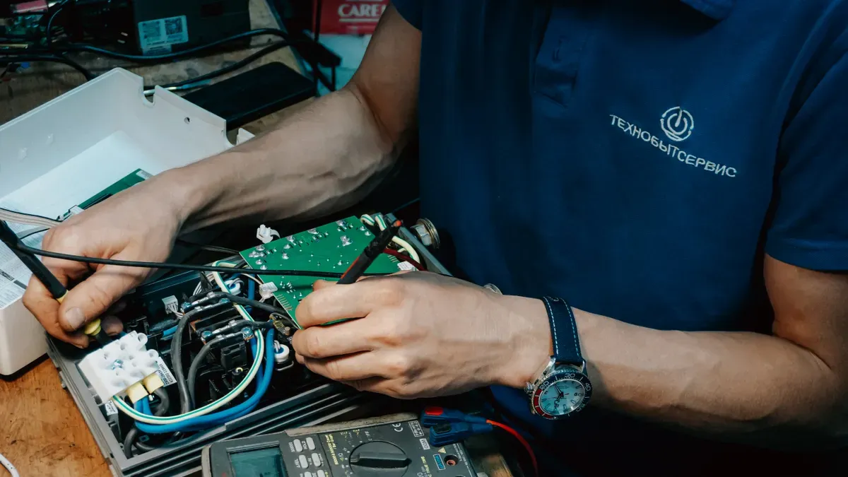
You can stop product defects early by setting up real-time checks on the SMT line. Finding flaws before reflow soldering protects vehicle electronics and ensures long-term system performance.
Solder Paste Inspection and Component Placement
Quality SMT printing starts with 3D solder paste checks right after stencil printing. The machine projects light patterns onto solder paste to build a 3D map. This system measures deposit volume, height, area, and placement against original Gerber files. Catching deposit issues early keeps process limits within 10% and stops solder bridges. Closed-loop feedback sends data directly back to the printer. The system adjusts squeegee pressure or cleans stencils when it spots printing drift.
| In-Line Strategy | Primary Focus | Key Implementation Detail |
|---|---|---|
| Stencil Design | Fine-pitch printing | Laser-cut stainless steel stencils ≤0.1mm thick with trapezoidal apertures |
| SPI Monitoring | Volume and alignment verification | Closed-loop feedback keeps paste tolerances within 10% |
| Precision Placement | Misalignment prevention | High-resolution placers with fiducials maintain tolerances under 30 microns |
Automated process control tracks solder paste thickness using simple Xbar-R charts. Pick-and-place machines then set tiny surface-mount parts onto the printed board. High-resolution tools use multiple marks to keep alignment error under 30 microns. An active tracking system watches coordinates and placement speed in real time. If a feeder jams, the system triggers a quick alarm. This early warning lets operators fix issues before making hundreds of bad boards. Using these top methods in high-reliability pcb assembly lines creates a strong setup for defect-free making.
Mitigating Voiding and Bridging in SMT Assembly
BGA and QFN parts need good heat control to prevent hot spots and electric breaks. Trapped gas creates solder pockets that weaken heat flow during normal vehicle use. You should apply advanced pcb assembly methods to clear gas pockets and ensure steady results across all car uses.
- Improve stencil design using windowpane openings sized at 80% to 90% of pad diameter to cut paste volume by 20% to 30% and let gas escape.
- Use a Ramp-Soak-Spike heat profile with a soak zone at 150°C to 180°C for 60 to 120 seconds to start flux and clean out gas.
- Keep a nitrogen space with oxygen levels at or below 500 ppm to improve solder flow and stop surface rust.
- Use vacuum heat tech while solder is liquid to pull trapped air pockets out of molten joints.
Vacuum reflow tech offers better strength compared to standard heating methods. Factory tests show that switching to vacuum heating lowers average BGA voids from nearly 18% to under 2%. Off-line X-ray checks prove solder strength by enforcing an acceptance limit of 10% or lower void area per BGA ball. Following these top practices prevents solder bridges and cracks in critical automotive uses.
A careful plan for high-reliability pcb assembly removes hidden heat flaws before installation. Modern car parts need constant checking to protect safety circuits. Joining automated tools with better heat plans keeps high standards across all high-reliability pcb assembly runs. This clear build method brings required strength while protecting total board output. Choosing car parts guards vehicle hardware, while running an automotive pcb assembly check ensures defect-free quality across plant lines.
Inspection Technologies Ensuring High Reliability

Automated Optical and X-Ray Inspection Systems
You build vehicle electronics to handle challenging conditions on the road. Automated optical inspection equipment photographs the surface of the board under multi-angle lighting. The software compares captured photos against design files to detect surface issues.
- High-resolution cameras capture images under varied lighting to highlight solder joints.
- Image processing software enhances details and looks for unexpected connections or excess solder between pads.
- Software algorithms compare images against design files to flag missing components, improper polarity, or misaligned parts.
- System logging records defect locations immediately to help factory teams take corrective actions.
Visible light cannot pass through opaque metal or silicon component packages. Automated X-ray inspection systems generate high-energy photons to solve this physical limitation. Materials like lead and tin absorb photons strongly and appear dark on digital images. Voids filled with air absorb less energy and appear bright. X-ray equipment reveals hidden solder bridges under ball grid arrays and detects head-on-pillow defects. The system measures projected void area against joint area to evaluate solder joint density. This non-destructive technique checks thermal-pad voiding in flat no-lead components and identifies internal registration issues across multi-layer pcb designs. Combining optical and X-ray technologies creates a multi-layered verification strategy. This complete approach catches surface flaws and internal defects before boards advance to final stages.
Environmental Testing and Component Traceability
Environmental Stress Screening for Field Reliability
You validate automotive pcb designs using environmental stress testing to prevent field failures. Thermal shifts cause material expansion inside multi-layer pcb layers. You run stress screening using ISO 16750 and JEDEC JESD22-A104 guidelines. Thermal shock chambers cycle boards rapidly between extreme hot and cold zones.
You expose automotive modules to elevated temperatures from 125–150°C for 48–120+ hours according to AEC-Q100 rules. This burn-in step weeds out early component failures under power load cycling. You apply vibration testing from 10 to 2,000 Hz using SAE J2380 standards. You run baseline vibration at 1.8gRMS for 19.8 hours to simulate one product lifetime. You increase vibration amplitude in 1.5 dB increments up to 4.3gRMS for 15.9 hours. These actions reveal hidden flaws before deployment in automotive applications.
Supply Chain Traceability and Counterfeit Protection
Fake automotive components cause over $7.5 billion in industry losses annually. Up to 15% of replacement parts are fake according to industry reports. You protect automotive applications against bad parts in the automotive sector through strict component tracking.
Traceability of materials prevents counterfeit parts from entering your assembly line and maintains critical safety standards across all production runs.
- You check lot tracking data to verify component records against official supplier databases.
- You run X-ray fluorescence analysis to inspect lead composition without damaging parts.
- You perform decapsulation on sample chips to examine internal die markings under magnification.
Full tracking ensures regulatory compliance and helps you isolate bad parts fast during recall events. You select high quality materials and follow strict storage methods to maintain product reliability. You enforce rigorous testing routines and apply best practices across every pcb manufacturing phase. KING FIELD provides electrical testing and high reliability testing to protect high-reliability pcb assembly projects for automotive devices. Our active process control safeguards board quality in automotive supply networks. You get high reliability performance for critical automotive applications. Partnering with KING FIELD secures high-reliability pcb assembly quality while protecting every automotive pcb layout. You get proven high-reliability pcb assembly results for every pcb build.
Getting zero-defect quality in car production needs tested factory methods. You have to follow strict rules to protect car electronics. Fast optical checks and stress testing find hidden flaws quickly. Using these good habits boosts system dependability and keeps vehicles safe.
FAQ
What quality rules control automotive pcb assembly?
You must follow IATF 16949 and ISO 9001 quality rules to join the supply line. These systems demand strict risk planning. Also, IPC-A-610 Class 3 sets physical rules for essential car uses.
Why do car parts need IPC-A-610 Class 3?
Car hardware handles intense heat and constant harsh bumping on the road. Class 3 enforces tight placement limits and strict solder hole rules. These checks defend your bare pcb from sudden road breakdowns.
How does line checking stop PCB defects?
Factory tools use 3D paste checks before setting tiny parts. Later, automated X-ray scanners spot secret BGA solder gaps. This constant checking keeps process drift safe and catches flaws early.
How do makers guard the car supply line against fake parts?
Factories track part groups to confirm real supply sources. Testers use X-ray light scans to check material makeup. These steps stop fake parts from reaching car building lines.