Designing and Manufacturing Industrial Controller PCBs: A Complete Guide
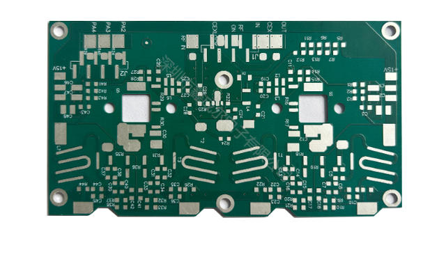
Industrial controller PCBs are essential components of modern machines. They ensure that systems operate accurately and efficiently under tough conditions. These industrial controller PCBs are designed to withstand high heat, strong vibrations, and heavy pressure. Their reliable performance makes them crucial for critical tasks.
For high-power applications, heavy copper PCBs are particularly beneficial. They facilitate the flow of electricity, preventing damage from overheating. These PCBs effectively dissipate heat, eliminating hot spots and maintaining system stability. Additionally, they exhibit durability under temperature fluctuations, making them ideal for industries such as aerospace and defense.
Through PCB production using advanced techniques, manufacturers create PCBs that perform well and have a long lifespan. These innovations enable machines to operate smoothly, even in challenging environments.
Key Takeaways
- Industrial controller PCBs help machines work well in tough conditions like heat and shaking.
- Use thick copper PCBs for strong power needs to stop overheating and keep systems steady.
- Follow rules like IPC and UL to make safe and reliable PCB designs.
- Testing and trying out designs are important to find and fix problems before making many copies, saving time and money.
- Add IoT features to your PCBs to improve how they work and share data quickly.
Understanding Industrial Controller PCBs
Definition and Purpose
Industrial controller PCBs are key parts of automated systems. They link parts like sensors, processors, and microcontrollers. This helps machines work smoothly and efficiently. These PCBs handle power, signals, and device communication. Their main job is to control industrial processes reliably. They keep systems precise and efficient where performance is critical.
Applications in Industrial Systems
Industrial controller PCBs are used in many systems. They run robots, assembly lines, and automated machines. In power plants, they manage turbines and generators. In transportation, they guide trains and traffic lights. They are also found in medical tools and aerospace systems. Their flexibility makes them vital for industries needing accuracy and strength.
Unique Requirements for Industrial Environments
Industrial settings have tough conditions like heat, vibrations, and interference. These PCBs need strong designs to handle such challenges. Heat-resistant and anti-corrosion materials are important. Coatings protect circuits from dust and moisture. Signals must stay clear to avoid disruptions. These PCBs also follow strict safety rules. Meeting these needs ensures they work well in harsh places.
Key Principles of Industrial Controller PCB Design
Ensuring Reliability and Durability
Reliability is very important for industrial controller PCBs. The PCB must handle tough industrial conditions. Choose materials that resist heat, rust, and stress. FR-4 with good heat properties is a common pick.
Durability is about the design too. Use thicker copper layers to carry high currents safely. Plated through-holes make the PCB stronger and better at conducting electricity. Add protective layers like conformal coatings or solder masks. These protect from water, dust, and chemicals.
Tip: Test your PCB in fake industrial settings to find weak spots before making many.
Managing Thermal Performance
Managing heat is key for your PCB’s performance. Industrial systems make a lot of heat, which can harm parts. Focus on ways to get rid of heat.
Use heat sinks and thermal vias to move heat away from parts. Place parts smartly to avoid heat building up in one spot. Heavy copper PCBs are great for high-power uses because they spread heat well.
Another way is using thermal interface materials (TIMs). They help move heat between parts and heat sinks. Spread out heat-making parts on the PCB.
Note: Bad heat management can cause overheating, leading to system failures or a shorter PCB life.
Signal Integrity and Noise Reduction
Signal integrity means your PCB sends data correctly. Reducing noise is also key, especially where electromagnetic interference (EMI) is common.
Use controlled impedance traces to keep signals clear. These traces stop signal distortion and keep communication steady. Shielding, like ground planes and metal covers, cuts down EMI.
Route traces properly. Don’t cross signal lines to avoid crosstalk. Keep high-frequency traces short and away from power lines. Use decoupling capacitors to steady voltage and cut noise.
Tip: Run signal integrity tests during design to spot problems early.
Compliance with Industry Standards
When making industrial controller PCBs, follow industry rules. These rules ensure your PCB works safely and reliably in tough places. They also help you meet laws and earn customer trust.
Here are some important industry rules to know:
- IPC Standards: These rules cover PCB design and making. IPC-A-610 checks soldering quality, and IPC-2221 covers general design needs.
- UL Certification: UL checks if your PCB is safe. It looks at fire safety and electrical insulation.
- RoHS Compliance: RoHS limits harmful stuff like lead and mercury in PCBs. This makes your product safer for the planet.
- ISO Standards: ISO 9001 checks quality control, and ISO 14001 focuses on eco-friendly practices. These show you care about quality and the environment.
Tip: Different industries need different rules. For example, aerospace and medical devices have stricter rules than others.
To follow these rules, use good materials and trusted methods. Test your PCB well to make sure it meets safety and performance needs.
Skipping these rules can cause product problems, legal trouble, and loss of trust. By following them, your PCB becomes more reliable, and your reputation improves.
Step-by-Step Process for Designing Industrial Controller PCBs
Gathering Requirements and Specifications
The first step is to know what the system needs. Gather all technical and functional details before designing. This includes the working environment, power needs, and signal types.
Ask questions like:
- What will the PCB do?
- What parts will it connect?
- What conditions, like heat or shaking, will it face?
Think about industry rules and certifications too. For example, medical or aerospace PCBs follow stricter rules. Writing down these needs helps avoid mistakes and saves time later.
Tip: Work with engineers and others to cover all important details.
Schematic Design and Circuit Simulation
After gathering needs, create a schematic. A schematic is a map showing how parts like resistors and chips connect. Use tools like Altium Designer or KiCad to draw it.
Next, simulate the circuit to test it virtually. This checks for problems like wrong connections or voltage issues. Tools like LTspice or Multisim help find and fix errors early.
Note: Testing the schematic well reduces mistakes during manufacturing.
PCB Layout and Design Tools
The PCB layout turns the schematic into a real design. Arrange parts and draw paths for signals on the board. Use space wisely while keeping signals clear.
Tools like Eagle, OrCAD, or Altium Designer can help. These tools have features like auto-routing and 3D views. Focus on trace width, spacing, and layers to handle current and signals properly.
Best practices for layout include:
- Keep high-power parts away from sensitive ones to avoid problems.
- Use ground planes to cut noise and improve stability.
- Make traces short and direct for better signal quality.
Tip: Check the layout carefully for mistakes before making a prototype.
Prototyping and Validation
Prototyping and validation are important steps for making industrial controller PCBs. These steps check if your design works before mass production. Testing a prototype helps find and fix problems early. This saves both time and money.
Building the Prototype
To make a prototype, create a few PCBs using your final design. Use the same materials and methods planned for the finished product. This ensures the prototype acts like the real thing.
When making the prototype, focus on:
- Component Placement: Make sure parts fit and match the design.
- Signal Testing: Check if signals move correctly through the board.
- Thermal Performance: Test how the PCB handles heat during use.
Tip: Choose a trusted PCB maker for prototypes. They can spot possible production issues.
Testing and Validation
After building the prototype, test it thoroughly. This ensures the PCB works well and meets all requirements.
Key tests include:
- Electrical Performance: Check voltage, current, and signal quality. Make sure the PCB works as expected.
- Environmental Resistance: Test the PCB in heat, vibrations, and moisture. This shows if it can survive tough conditions.
- Compliance with Standards: Confirm the PCB meets rules like IPC and UL certifications.
Use tools like oscilloscopes and thermal cameras for testing. These tools help find hidden problems.
Iterating the Design
Testing often shows areas to improve. Use feedback to fix your design. For example, if overheating happens, move parts or add thermal vias.
After changes, make another prototype and test again. Repeat this process until the PCB is ready for production.
Note: Skipping testing can cause big problems later. Always test carefully to avoid failures.
By spending time on prototyping and validation, you can make a strong PCB. This step improves product quality and earns customer trust.
Material Selection for Industrial Controller PCBs
Substrate Materials for Industrial Applications
Picking the right substrate is key for a strong PCB. Substrates are the base of the board, giving support and insulation. For industrial use, materials must handle heat, stress, and chemicals well.
FR-4 is a popular choice. It is strong and resists heat. For tougher jobs, ceramic-based or polyimide materials work better. They handle very high heat and stay stable in harsh conditions.
Tip: Match the substrate to your system’s needs to avoid problems.
Conductive Materials and Their Properties
Conductive materials move electricity through the PCB. Copper is the most common because it is cheap and works well. For industrial PCBs, thicker copper layers are often needed. They carry more current and lower resistance.
Sometimes, silver or gold plating is added to parts. This improves conductivity and stops rust. These materials cost more and are used in special cases.
Note: Thicker copper also helps the PCB manage heat better.
Protective Coatings for Harsh Environments
Industrial settings can harm PCBs with dust, water, and chemicals. Protective coatings keep the board safe and last longer. Conformal coatings, like acrylic or silicone, are often used. They protect while letting heat escape.
For very tough conditions, potting compounds or encapsulation are better. These fully cover the PCB for maximum protection.
Tip: Pick a coating that protects but is easy to fix if needed.
Manufacturing Process for Industrial Controller PCBs
Fabrication Techniques
Making a PCB starts with preparing the base material. This base, called the substrate, supports the PCB. Manufacturers use methods like photolithography to design circuits. This involves covering the base with a light-sensitive layer and shining UV light through a stencil.
After the circuit pattern is made, conductive layers are added. Copper is the usual choice for these layers. It is applied using electroplating or lamination. Next, holes are drilled into the board for parts and connections. These holes are coated to allow electricity to flow.
Tip: Pick a fabrication method that fits your PCB’s design and use.
Assembly and Component Placement
Assembly is when parts are added to the PCB. Pieces like resistors, capacitors, and microcontrollers are placed on the board. Machines do this job to ensure accuracy. Surface-mount technology (SMT) is often used. SMT lets parts stick directly to the PCB without wires.
Once parts are placed, soldering secures them. Reflow soldering is common for SMT boards. The PCB goes through a heated oven, melting the solder to attach parts. For bigger parts, wave soldering may be used instead.
Note: Good assembly helps the PCB work well in tough systems.
Quality Control and Testing
Testing checks if the PCB works and is safe. Electrical tests look for problems like broken connections or short circuits. Automated optical inspection (AOI) scans for mistakes like misplaced parts or bad soldering.
Environmental tests check the PCB’s strength. The board is tested against heat, water, and shaking to mimic real conditions. These tests prove the PCB can survive harsh places.
Tip: Always test carefully to avoid expensive problems later.
Advanced Technologies in Industrial Controller PCB Design
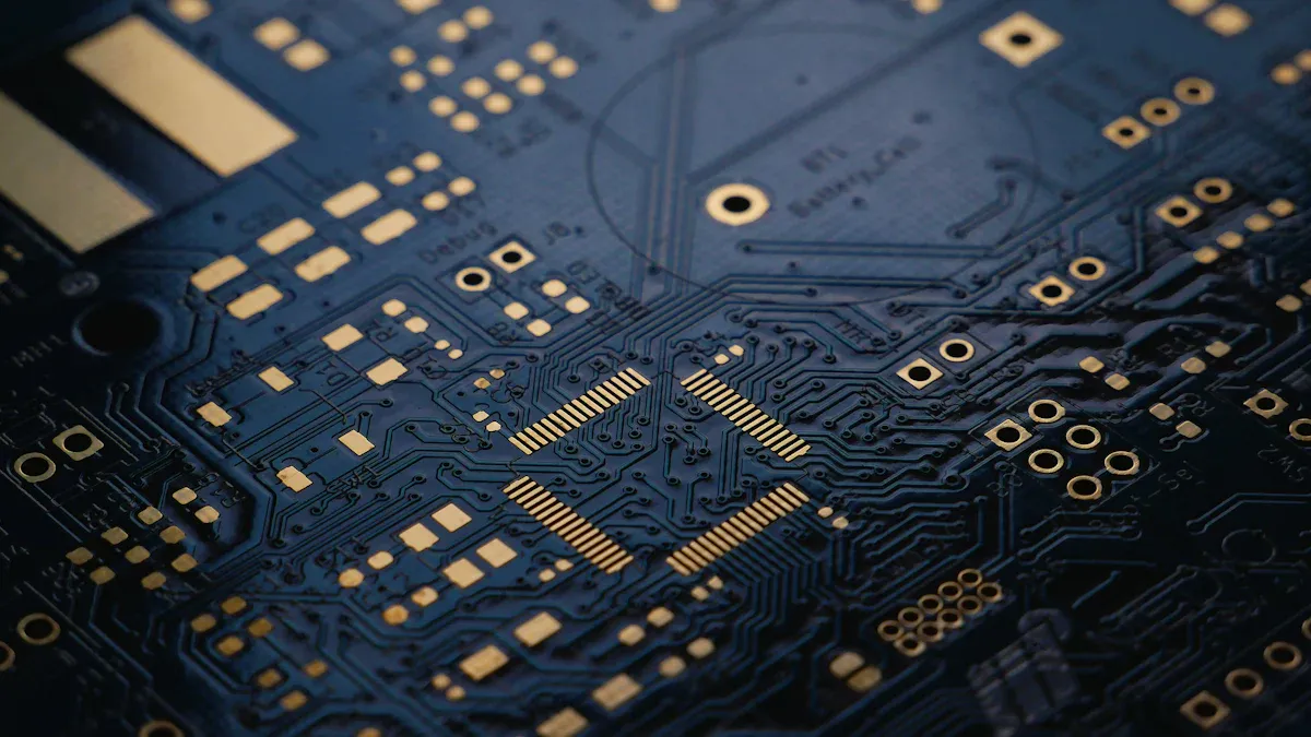
High-Density Interconnect (HDI) PCBs
HDI PCBs are changing how modern systems work. They use smart methods to fit more connections in small spaces. This makes them great for small, powerful devices. One special feature is microvia technology. It uses lasers to drill tiny, exact holes. These holes link PCB layers, making them work better.
Another method is sequential lamination. This process adds extra layers to the PCB, boosting its capacity. HDI PCBs also allow very dense wiring. This means more connections fit in less space, which is useful for industries like cars and airplanes.
| Feature | What It Does |
|---|---|
| Microvia technology | Laser-drilled holes for accuracy |
| Sequential lamination | Adds layers for more connections |
| Ultra-high wiring density | Packs more connections in small areas |
| Applications | Phones, cars, aerospace |
These features make HDI PCBs a smart pick for industries needing small, efficient designs.
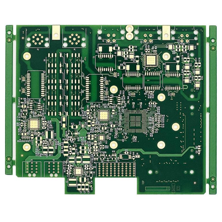
Multi-Layer PCB Designs
Multi-layer PCBs are key for tough industrial jobs. They have many layers of conductive material stacked together. This design helps them handle more signals and power. Using multi-layer PCBs can shrink your system while making it do more.
These PCBs also keep signals clear. Ground planes in the layers cut down noise and interference. This makes them perfect for fast systems. Industries like telecom and medical tools depend on multi-layer PCBs for advanced setups.
Tip: Choose multi-layer PCBs when you need strong performance in tight spaces.
Integration of IoT and Smart Technologies
IoT and smart tech have changed how PCBs are made. Sensors, wireless parts, and processors can now be built into the PCB. This lets machines share data and talk to each other in real time.
For example, IoT PCBs can check machine health and send alerts for repairs. Smart tech also saves energy by adjusting power use as needed. These features make IoT PCBs a great tool for modern industries.
Note: Adding IoT features to your PCB can make it smarter and ready for the future.
Addressing Challenges in Industrial Controller PCB Design
Thermal Management Solutions
Handling heat is a big problem in PCB design. Too much heat can harm parts and shorten the system’s life. To fix this, use good ways to manage heat.
Pick materials that move heat well, like copper layers. Thermal vias help carry heat away from important parts. Add heat sinks or fans to cool things down. Spread out heat-making parts to stop hot spots.
Another way is using thermal interface materials (TIMs). These fill gaps between parts and heat sinks, helping heat move better. Test your PCB in real conditions to check if your heat solutions work.
Tip: Watch your PCB’s temperature while it works to catch overheating early.
Balancing Cost and Performance
Keeping costs low while making a good PCB is important. Using top materials and features can cost more, but skipping them may cause problems.
Focus on what your system really needs. Pick materials that fit your design without overdoing it. Use multi-layer PCBs only if your design requires them.
Save money by planning the layout well. Using space wisely reduces waste. Work with trusted makers to get good quality at fair prices.
Note: Spending more on strong and reliable designs saves repair costs later.
Ensuring Long-Term Reliability
Industrial PCBs must last a long time. Use strong materials and protective layers to make them durable. Substrates like FR-4 or polyimide are good choices. Conformal coatings protect against water, dust, and chemicals.
Testing is very important. Try out your PCB in tough conditions like heat and shaking to find weak spots. Regular checks and fixes also help your PCB last longer.
Tip: Keep records of your tests to track how well your PCB works and improve it.
Future Trends in Industrial Controller PCB Manufacturing
AI and Machine Learning in PCB Design
AI and machine learning are changing how PCBs are made. These tools handle hard tasks, making fewer mistakes and working faster. AI tools study your design to improve layouts and find problems early. Machine learning helps with signal paths and heat control by learning from past designs.
AI can test how a PCB works in different situations. This shows weak spots before production starts. It also improves quality checks by spotting errors during assembly. For example, smart inspection systems use machine learning to find bad soldering or misplaced parts.
The need for AI in PCB making is growing fast. High-tech computers and AI chips use special bases like ABF. These bases handle heat well and stay stable, which is important for modern devices.
Advancements in Materials Science
New materials are making PCBs better. They help manage heat, keep signals clear, and last longer. For tough jobs, you need bases that survive harsh conditions. Ceramic and polyimide materials are popular because they resist heat and stay strong.
Better conductive materials also help PCBs work well. Thicker copper layers carry more electricity and spread heat better. Silver and gold coatings improve conductivity and stop rust. These upgrades make PCBs stronger and more efficient.
ABF bases show these changes. They lower signal loss and handle heat better. These features are key for industries like aerospace and telecom, where accuracy matters most.
Sustainability and Eco-Friendly Manufacturing
Making PCBs in a green way is becoming important. You can cut waste and save energy by using eco-friendly methods. Renewable energy during production lowers harm to the planet. Recycling copper and other materials also helps.
Europe leads in green PCB making. Renewable energy and smart systems push for cleaner practices. These efforts support using advanced bases like ABF. By going green, you match global goals to protect the environment.
Eco-friendly coatings and lead-free soldering are other ways to make PCBs safer for the planet. These methods follow rules like RoHS and make products safer.
Tip: Using green methods helps the planet and boosts your company’s image.
Making industrial controller PCBs needs good planning and careful work. Start by knowing what the system needs, then design and test prototypes. Each step makes sure the PCB works well in tough places. Picking strong materials and using smart methods makes the PCB last longer.
Using new ideas like IoT and AI helps make better PCBs. These tools make designs faster and fix mistakes. Green practices also help protect the planet while making PCBs.
To make your PCB better, focus on heat control and clear signals. Test prototypes to find problems early. Work with skilled makers to get strong PCBs that follow the rules.
FAQ
What makes industrial controller PCBs special compared to regular PCBs?
Industrial controller PCBs are built for tough conditions. They can handle heat, shaking, and moisture. Strong materials, thick copper, and protective layers make them reliable. Regular PCBs don’t have these features.
How do you pick the right material for an industrial PCB?
Think about where it will be used. For high heat, choose polyimide or ceramic bases. For normal use, FR-4 is a good option. Match the material to the system’s heat, power, and strength needs.
Tip: Ask your PCB maker for advice on materials.
Why is managing heat important in industrial PCBs?
Too much heat can break parts and shorten the PCB’s life. Good heat control keeps it working well. Use heat sinks, thermal vias, and smart part placement to cool it down.
Can IoT features be added to industrial PCBs?
Yes, you can add IoT parts like sensors and wireless tools. These let machines share data and work smarter. They also help with real-time monitoring.
Note: Make sure your design has enough space and power for IoT parts.
How do you check if an industrial PCB is reliable?
Test it in fake tough conditions like heat, shaking, and wetness. Use tools like oscilloscopes to check signals and thermal cameras to see heat. These tests make sure it works safely and meets standards.
Tip: Always test prototypes before making a lot of PCBs.