Resistor Color Code
The resistor color code is a standardized system that helps you identify the resistance value and tolerance of a resistor. This method uses colored bands printed on the resistor’s body. Each color corresponds to a specific number or multiplier, allowing you to quickly decode critical information without additional tools.
Key Takeaways
- Resistor color codes help you find resistance and tolerance easily.
- Knowing the color bands lets you read resistor values fast.
- Mnemonics and flashcards can help you learn the color order.
Purpose and Importance of Resistor Color Codes
Why resistors use color codes
Resistors use color codes to simplify the identification of their resistance values and tolerances. This system eliminates the need for additional tools, allowing you to quickly determine a resistor’s specifications by observing its color bands. The resistor color coding system is especially useful in modern circuit design, where efficiency and accuracy are critical.
- Color codes make it easy to read resistance values, ensuring proper circuit functionality.
- They reduce the risk of errors during assembly and testing.
- A resistor color code chart provides a visual reference for decoding the bands, saving time during design and troubleshooting.
For example, the 2K resistor from PCBasic uses color bands to indicate its resistance value of 2000 ohms and tolerance. This ensures that you can confidently integrate it into circuits like voltage dividers or current-limiting configurations without miscalculations.
Benefits of standardization in electronics
Standardization in electronics, including the use of resistor color codes, offers numerous advantages. It ensures consistency across components, simplifies circuit design, and reduces errors during manufacturing and assembly.
| Resistor Type | Precision Level | Applications | Benefits of Color Code |
|---|---|---|---|
| 3-band | Less precise | Low-cost, general-purpose | Easy identification, quick calculations, reduces errors |
| 4-band | Moderate precision | General electronics | Improved accuracy, reduces rounding errors |
| 5-band | High precision | Signal processing, measurement instruments | Ensures consistent performance, critical for functionality |
Standardized resistor color coding also supports various applications:
- Voltage dividers maintain expected voltage levels with accurate resistance values.
- Amplifiers rely on precise resistors to ensure gain stability and consistent performance.
By adopting standardized resistor color codes, you can streamline your design process and ensure compatibility across different components. This system has evolved over decades, with milestones such as the IEC 62:1952 standardization and the current IEC 60062:2016 guidelines. These developments highlight the importance of uniformity in electronics, making resistor color codes an indispensable tool for engineers and technicians.
How to Read Resistor Color Codes

Meaning of the color bands
Understanding resistor bands is essential for identifying a resistor’s value and tolerance. Each resistor features a series of colored bands, with each color representing a specific digit, multiplier, or tolerance. These bands are read from left to right, starting with the band closest to one end of the resistor.
The first two or three bands (depending on the resistor type) indicate the significant digits of the resistance value. The next band represents the multiplier, which determines the power of ten by which the significant digits are multiplied. Finally, the last band specifies the tolerance, which indicates the allowable deviation from the stated resistance value.
Here’s a detailed breakdown of the color bands:
| Color | Digit | Multiplier | Tolerance |
|---|---|---|---|
| Black | 0 | 1 | |
| Brown | 1 | 10 | ± 1% |
| Red | 2 | 100 | ± 2% |
| Orange | 3 | 1,000 | |
| Yellow | 4 | 10,000 | |
| Green | 5 | 100,000 | ± 0.5% |
| Blue | 6 | 1,000,000 | ± 0.25% |
| Violet | 7 | 10,000,000 | ± 0.1% |
| Grey | 8 | ± 0.05% | |
| White | 9 | ||
| Gold | 0.1 | ± 5% | |
| Silver | 0.01 | ± 10% |
This table serves as a quick reference for decoding resistor values. For example, a resistor with red, violet, and orange bands has a resistance of 27,000 ohms (27 × 1,000).
Steps to interpret resistor values
Decoding a resistor’s value using its color bands is straightforward when you follow these steps:
- Identify the orientation: Locate the band closest to one end of the resistor. This is the starting point for reading the color code.
- Read the significant digits: Note the colors of the first two or three bands (depending on the resistor type) and match them to their corresponding digits in the resistor color code chart.
- Determine the multiplier: Identify the color of the next band and find its multiplier value. Multiply the significant digits by this value to calculate the resistance.
- Check the tolerance: Observe the last band to determine the tolerance. This value indicates the acceptable range of variation in the resistor’s resistance.
- Verify your calculation: Cross-check your result with a resistor color code chart to ensure accuracy.
For instance, if a resistor has the bands yellow, violet, red, and gold, you can decode its value as follows:
- Yellow (4) and violet (7) form the significant digits: 47.
- Red (100) is the multiplier: 47 × 100 = 4,700 ohms.
- Gold (±5%) is the tolerance: The resistance can vary between 4,465 and 4,935 ohms.
Resistor color code chart
To simplify the process of decoding resistor values, you can use a resistor color code chart. This chart provides a visual representation of the color bands and their corresponding values. Below is an example of such a chart:
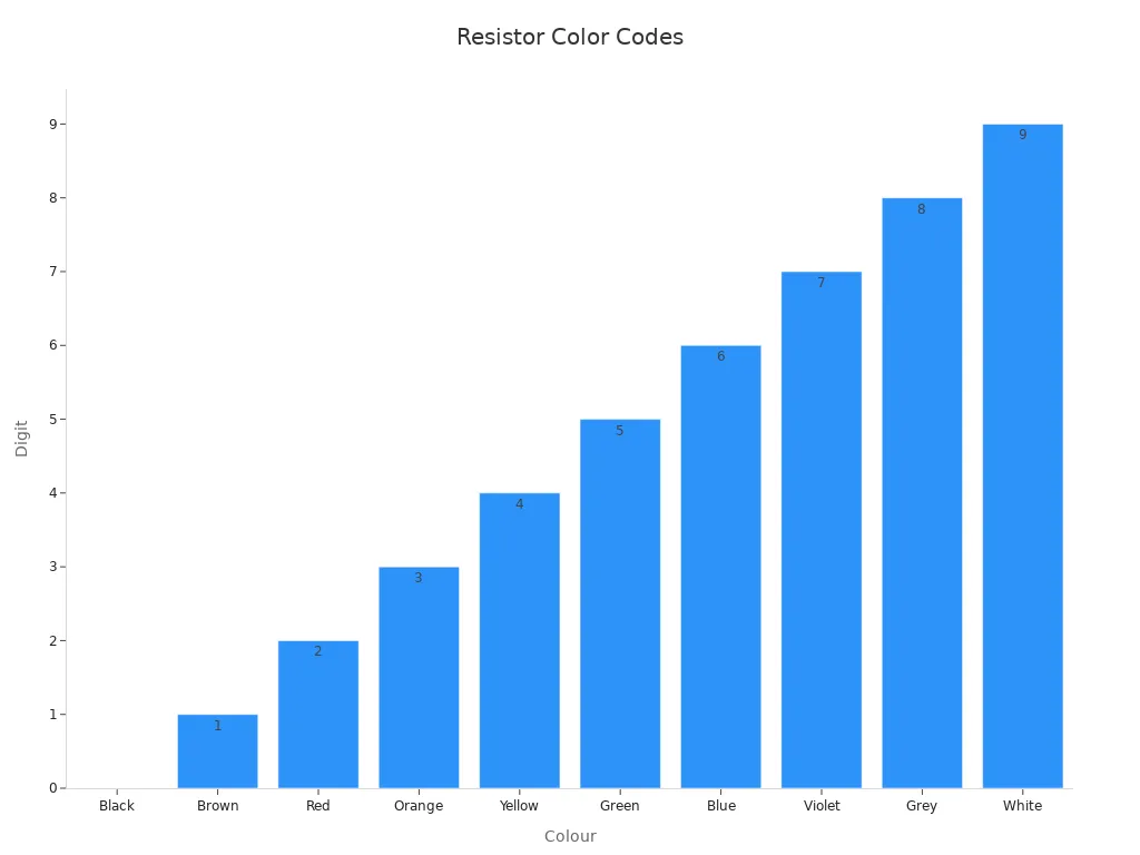
Using this chart alongside the steps outlined above will help you quickly and accurately determine resistor values. Whether you’re working on a simple educational project or a complex circuit design, knowing how to read color codes ensures precision and efficiency.
Memorizing Resistor Color Codes
Mnemonics for color sequence
Memorizing the resistor color code can feel overwhelming at first, but mnemonics simplify the process. A popular mnemonic, “B.B. ROY of Great Britain has a Very Good Wife,” helps you recall the order of colors: Black, Brown, Red, Orange, Yellow, Green, Blue, Violet, Gray, and White. Each word corresponds to a color in the sequence, making it easier to remember.
Mnemonic devices work by creating associations or patterns that enhance memory retention. They transform abstract information into something relatable or rhythmic, which improves recall. For resistor color codes, this technique is particularly effective because it organizes the sequence into a memorable phrase. Whether you’re a student or a professional, using mnemonics can save time and reduce errors when working with resistors.
Tip: Practice saying the mnemonic aloud while visualizing the colors. This reinforces the connection between the phrase and the color sequence.
Tips for quick recall
To quickly recall resistor color codes, you can combine mnemonics with other strategies. Here are some practical tips:
- Use flashcards: Write the color on one side and its corresponding digit on the other. Review them regularly to strengthen your memory.
- Practice decoding: Work with real resistors or images of resistors. Identify their values using the color bands.
- Group similar colors: Notice patterns, such as warm colors (Red, Orange, Yellow) representing smaller values and cool colors (Green, Blue, Violet) representing larger ones.
- Leverage repetition: Repeatedly decode resistor values to build familiarity with the sequence.
By combining these techniques, you can master how to memorize resistor color codes effectively. Over time, recalling the sequence will become second nature, allowing you to focus on designing and troubleshooting circuits with confidence.
Resistor Types and Their Color Codes

Wire Lead Resistors
Wire lead resistors are among the most common types used in electronic circuits. These resistors feature cylindrical bodies with axial leads extending from both ends, making them easy to mount on breadboards or solder onto printed circuit boards (PCBs). Their color-coded bands provide a quick way to identify resistance values and tolerances.
You can decode wire lead resistors using the standard color code system. Each band represents a digit, multiplier, or tolerance. For example, a resistor with red, violet, yellow, and gold bands has a resistance of 27 kΩ and a tolerance of ±5%. This coding system ensures accuracy during circuit design and assembly.
Wire lead resistors are ideal for applications requiring durability and versatility. They are commonly used in power supplies, audio amplifiers, and voltage regulators. Their robust construction allows them to handle higher power ratings compared to other resistor types.
Tip: When working with wire lead resistors, ensure proper orientation when reading the color bands. This prevents errors in decoding resistance values.
Chip Resistors
Chip resistors, also known as surface-mount resistors, are compact components designed for modern electronics. Unlike wire lead resistors, chip resistors lack axial leads and are soldered directly onto PCBs. Their small size makes them suitable for high-density circuit designs, such as smartphones and microcontrollers.
The resistor color code system applies differently to chip resistors. Instead of color bands, manufacturers often use alphanumeric markings to indicate resistance values. However, the principles remain the same—digits and multipliers define the resistance, while tolerances specify the allowable variation.
- Chip resistors offer several advantages:
- Their compact design saves space on PCBs.
- They support automated assembly processes, improving efficiency.
- Their precision ensures reliable performance in sensitive circuits.
Chip resistors are widely used in signal processing, timing circuits, and current-limiting applications. Their ability to integrate seamlessly into complex designs makes them indispensable in modern electronics.
Note: When selecting chip resistors, verify their markings and specifications to ensure compatibility with your circuit requirements.
Resistor color codes simplify the identification of resistance values and tolerances, ensuring accuracy in circuit design. You can decode resistors efficiently by understanding the color bands and their meanings. For example, a resistor with red, violet, and gold bands represents 27 ohms with ±5% tolerance.
| Resistor Color Bands | Resistor Value | Tolerance |
|---|---|---|
| Red, Violet, Gold | 27 Ohms | ± 5% |
| Brown, Black, Silver | 10 Ohms | ± 10% |
Apply this knowledge by practicing with real components and using charts for quick reference. This skill enhances your ability to design reliable circuits and troubleshoot effectively.
FAQ
What is the purpose of the resistor color code?
The resistor color code helps you quickly identify resistance values and tolerances without additional tools. It ensures accuracy and efficiency in circuit design and troubleshooting.
How do you determine the tolerance of a resistor?
Check the last color band on the resistor. For example, gold represents ±5%, silver indicates ±10%, and other colors specify tighter tolerances like ±1% or ±2%.
Can you use a resistor color code chart for all resistor types?
Yes, you can use the chart for wire lead resistors. However, chip resistors often use alphanumeric markings instead of color bands for resistance identification.
Tip: Keep a resistor color code chart handy for quick reference during circuit assembly or repair. It saves time and minimizes errors.